On this page
Why reclaim the carrier
A communications link has two parts you can name separately. The bearer is the physical path the signal travels: a stretch of radio between two antennas, or a run of wire between two points. The network is the addressing and routing that turns that path into a way to reach a particular node. You build bearers here. The network that rides them, Reticulum, is Module 09; here you reclaim the path it will run on and stop there.
Module 04 established the salvage thesis for hardware: the city discards working material at scale, and reclaiming it costs a teardown instead of a purchase. The same is true of the communications carrier. A satellite dish is a precision reflector that was bolted to a roof, paid for, and abandoned when the service lapsed; the structured cabling inside an emptied office is copper that was pulled, terminated, and left in the walls. Both were installed at cost by someone who is gone. You reclaim the physical path a signal travels instead of renting it back from a carrier.
Reclaiming the bearer gives two things a bought link cannot. The first is independence from a provider who can raise a price, throttle a link, or switch it off. The second is signature: a wired bearer emits nothing a receiver can find, and a repurposed dish concentrates its energy into a narrow beam that is hard to intercept off to the side. The doctrine of this module is capable and quiet: a link that carries real traffic while giving a listener as little as possible.
Unit 02 places the modern emitter away from your position. Units 03 and 04 pull a discarded dish and aim it. Units 05 and 06 find, terminate, and test a reclaimed ethernet run. Units 07 to 09 work a dead phone pair: find the boundary, prove the pair is dead, drive it. Unit 10 connects the sited terminal to whichever bearer you built. Each unit ends with a result you can observe before you go on to the next.
Site the emitter away from you
A Starlink terminal or a cellular hotspot is capable, and this module keeps it. The problem it creates is not capability. The problem is that it is a transmitter running continuously at your position, and a transmitter at your position is a thing that can be found. The answer is not to give up the capability. It is to move the emission away from you and reach it over a bearer that emits nothing, which is what the rest of this module builds.
A Ukrainian Armed Forces methodological guide on protecting Starlink terminals from enemy electronic warfare states the underlying fact plainly: “radio access via Starlink terminals shares the drawbacks of any radio link…the possibility of influence (detection and suppression) by enemy EW.”1 The terminal “continuously emits a radio signal” toward the satellites overhead,1 so it is on the air the whole time it is connected. It also carries a GPS receiver and “determine[s] their own position” to adapt to the satellites available at that location,1 so the device holds and reports its own location. Its narrow upward beam does resist jamming from the side: the guide notes a terminal “emits a narrow-beam radio signal vertically upward, whereas EW stations cover a large area in the horizontal plane,” so an attacker “would need a powerful jamming system organized directly next to the user's antennas.”1 Directivity is not concealment, though, and the guide's own conclusion is that electronic warfare “most negatively affects Starlink terminals (up to no connection) only during setup and preparation from a cold… position.”1
The doctrinal answer is to separate the emitter from the position, and it is not ours. The same guide lists among its protection measures “remoting radio-emitting assets to maximum distance from command-post elements with remote operation.”1 A signature-management guide gives the same instruction from the other direction: its MASK method directs you to “place CP, vehicle, and manpack antennas behind barriers, buildings, woods, or hills,” and its WIRE method exists to “communicate with remote antenna sites, OPs, and security posts.”3 Put the emitter somewhere else, and run wire to it. That is standing doctrine, and a reclaimed bearer is what you run.
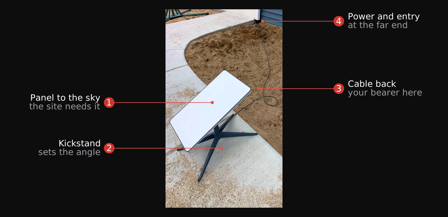

The current hardware hands off exactly what you need, and the small terminal is the one to remote. The Mini is the better emitter to place away from you, for four reasons its specification gives. It is “Starlink with Integrated WiFi,” one unit rather than a dish plus a separate router.18 It weighs 1.10 kg on its own and 1.53 kg with the kickstand and cable,18 so one person carries and sites it. It draws an average of 25 to 40 W against an input rating of “12-48V 60W”,18 which is a battery-and-panel load from Module 05 rather than a generator load, and it ships with a DC power cable so it runs from a bank without an inverter. And it provides “One (1) Latching Ethernet LAN port with Starlink Plug”,18 which is the hand-off to your reclaimed bearer.
The larger Standard kit remotes the same way with more to carry. It ships as a dish, a kickstand, a Router 3, and a “Starlink Cable 15 m (49.2 ft)”,17 and that cable is a fixed length between the dish and its router, so you do not stretch it: you remote the whole kit and carry the connection back from there. Router 3 provides “Two (2) Latching Ethernet LAN ports with removable cover”,17 and the kit draws an average of 75 to 100 W,17 two to three times the Mini's load, which is the real cost of the bigger terminal at a remote site. Older kits had no built-in ports at all and needed a separately sold ethernet adapter, so check what you have before you plan the run.
The terminal you remote is also a WiFi access point, and that is a second emitter at the far site. Both current kits carry a WiFi radio: the Mini is “Starlink with Integrated WiFi”18 running “802.11a/b/g/n/ac”,18 and the Standard kit's router runs “802.11 a/b/g/n/ac/ax” on a “Tri Band 4 x 4 MU-MIMO” radio.17 Site the kit and walk away, and it beacons a network name from the remote position continuously, on a band any phone in the area can see. The satellite uplink is the emission you moved deliberately. The WiFi is one you did not.
The control is the manufacturer's own: bypass mode, a setting that disables the built-in router's WiFi so a third-party router runs the network instead, enabled from the Starlink app.19 With it on, the terminal hands off over its ethernet port and radiates only its uplink, which is the state to leave it in at the far end. Turning it off again takes a factory reset,19 so set it deliberately rather than to see what happens.
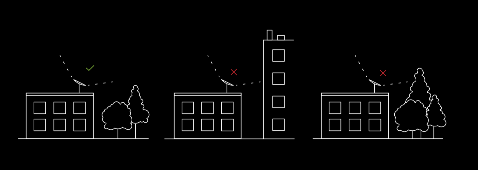
Five steps settle the remote site, and a site that fails any one of the first four is not the site.
- Find open sky for the terminal, not for yourself. The terminal points upward at the satellites, so its site needs open sky above it. Your own position does not, which is why the two can be separated at all.
- Put power at the far end. Size the supply to the terminal you are placing: 25 to 40 W average for the Mini,18 75 to 100 W for the Standard kit.17 That is a Module 05 problem to solve at the far end before you carry the terminal there, not after.
- Keep cover between the site and your position. The signature guide instructs you to place antennas “behind barriers, buildings, woods, or hills.”3 Terrain or structure between the emitter and your position is what makes the separation worth the cable.
- Choose a site an existing bearer route already reaches. The distance you can put between the emitter and yourself is set by the path you can reclaim, whether that is a wall run, a riser, or a dish shot. Pick a site the bearer reaches, then confirm the other three requirements hold there.
- Put the terminal in bypass mode before you site it. The setting disables the built-in router's WiFi so your own equipment runs the network,19 which removes a beacon from the remote position. Turning it off again needs a factory reset,19 so do it while the kit is still in your hands.
- Confirm the hand-off port. Look at the terminal you actually have and find the ethernet LAN port you will run the bearer from, one on the Mini18 and two on Router 3.17 If the kit has none, you need the adapter before you go to the site, not while you are standing at it.
Verify: a named site with open sky, a power source sized to the terminal, cover between it and your position, and one ethernet port to hand the bearer.
Pull the dish and fit the feed
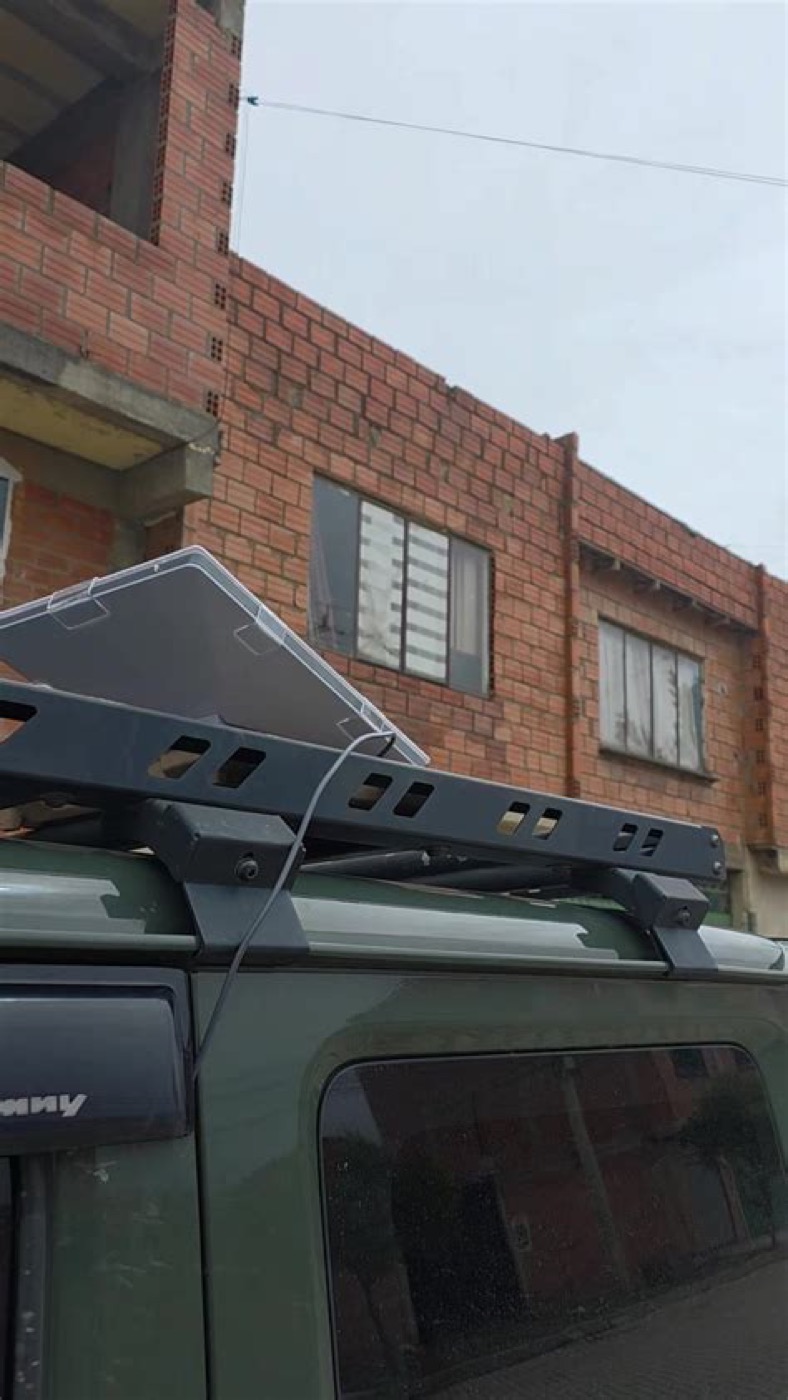
A discarded satellite dish is a parabolic reflector on a mount, and turning it into a directional link between two points you control costs a teardown and a feed. Module 06, Unit 07 gives the physics you are applying: the reflector is nonresonant geometry, the small feed antenna at its focus sets the band, and the gain follows from the diameter-to-wavelength ratio. Take the dish down first, then fit the feed.
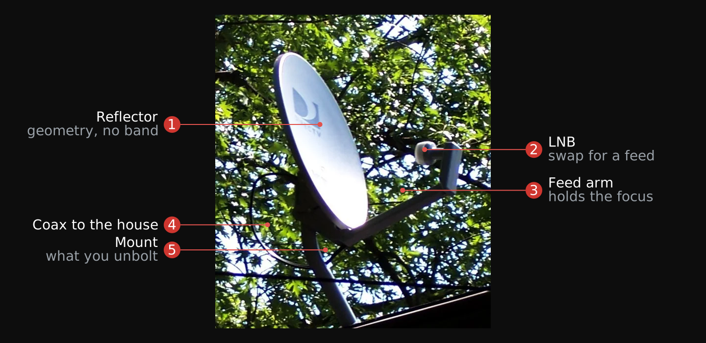
A television or old satellite-internet dish is a parabolic reflector 60 cm to a metre across. Its original feed pointed at a satellite band you will not use, so the reclaim is a feed swap: the reflector works over a wide range of frequencies and the feed alone decides the band. What you fit is a feed cut for one of the license-free bands, 2.4 GHz or 5.8 GHz. Module 04's teardown method covers the removal itself, applied here to a dish.
- Photograph the dish in place before you touch a bolt. The mount, the feed arm, and the angle the reflector sits at are all information you will want back, and none of it survives the removal. Module 04's rule applies here: photograph any step you are not sure you can reverse.
- Clear the overhead before you lift anything. Look up and find every power line near the dish and near the path you will carry it along. A reflector is a wide metal object on a mount, and it stays clear of every line while you raise, move, or lower it. If you cannot keep that clearance, this is not your dish.
- Disconnect the coaxial cable at the dish. The lead running to the house comes off the feed first, so nothing is under tension when the mount comes loose. Keep the cable if it is in good condition; it is reclaimable in its own right.
- Unbolt the mount, not the reflector. The reflector is the part with value and the part that deforms. Take the assembly off at the mount and carry it whole. A dented reflector no longer holds the geometry the gain depends on, so it is handled as a precision surface from here on.
- Strip it to the reflector, the feed arm, and the mount. The low-noise block at the focus is cut for a satellite band you will not use, so it comes off. The feed arm stays: it holds the focus, and its position is what you are about to reuse.
- Mount your own feed at the focus. Fit the feed cut for your band at the exact point the original occupied. That point is the reflector's focus, and a feed off it scatters the gain the dish geometry exists to collect. Measure the original position before you remove the old feed, and set the new one to it.
- Confirm the reflector is true. Sight across the surface for dents and check that the feed arm is not bent. Both faults show up later as a link that will not peak, and both are cheaper to find on the bench than on the mount.
Verify: a stripped reflector on its mount, undented, with a feed for your band held at the focus the original feed occupied.
Aim the dish link
The gain is a ceiling, not a promise. Module 06's formula gives a 60 cm dish at 5.8 GHz about 28 dBi at the 50 percent efficiency a reference calls nominal, and more on paper at the textbook 55 to 70 percent. A repurposed dish does not reach that. Measured field dishes run 10 to 50 percent efficiency, which sits 0.4 to 7.4 dB below the 55 percent book figure, so treat any published or computed gain as a ceiling and plan the link on the derated number. A dish you reclaimed, refed, and aimed by hand belongs at the low end of that range until you measure otherwise. Enter the derated gain into the Module 06 link budget, not the catalogue figure.
Interactive Dish derate Set a reclaimed dish and a band, and read the gain the link budget should actually carry against the catalogue ceiling. Open it full screen →Gain is paid for in a narrow beam, and a narrow beam must be aimed. The same 60 cm dish has a half-power beamwidth near 6 degrees, so the far station sits inside a cone only a few degrees wide and the dish is useless until it points there. Aiming has a coarse step and a fine step.
- Get the bearing to the far station. Take the azimuth from a map or from the two GPS positions. For a narrow-beam antenna “great accuracy is required to determine azimuth,” and unless a line of known azimuth is on the site, “the direction of the path is best determined by a magnetic compass.”4
- Correct the compass for declination. The bearing you took from the map is true; the compass reads magnetic. Apply the local magnetic declination so the compass reads true,4 or the dish starts its search pointed several degrees off a beam only six degrees wide.
- Swing the dish to that bearing and stop. This is coarse aim, and it is finished when the dish points at the corrected bearing. It gets the far station somewhere inside or near the beam. It does not peak the link, and no signal reading is used yet.
- Sweep azimuth a degree at a time. From the starting azimuth, “slowly swing the antenna in one direction,” moving “a degree at a time and then pause to let the signal measurement stabilize.”5 Go “very slowly at first or you will move right past the signal before the radio displays anything.”5
- Overshoot the peak, then come back. When the reading maxes out, do not stop there. “Once you max out the signal, keep going past it by a few degrees to verify that the signal level decreases,” then “come back to the maximum signal.”5 This step is what separates a true peak from a sidelobe, a smaller off-axis lobe that reads like a signal but leaves most of the gain on the table.
- Refine in half-degree steps. Repeat the sweep across the peak in half-degree increments to settle the azimuth.5
- Repeat for elevation. Run the same sweep in the vertical axis. The procedure notes elevation aiming is “usually only needed with very high gain antennas,”5 so on a small dish it is a small correction, not a second search.
- Lock the mount while watching the reading. “Monitor the signal strength while you tighten everything down,” because “it's not unusual for the antenna to move while you tighten the clamps.”5 If the reading falls as the clamps go tight, back off, re-peak, and tighten again.
Verify: a signal reading that falls off on both sides of where the dish now points, holding steady with the mount locked, and a recorded azimuth and elevation.
A dish concentrates its energy into that few-degree cone, so a listener off to the side receives very little of it. That is the same tight-beam property Unit 02 credited to the Starlink terminal's own narrow beam: capable on axis, quiet off it.
Find a reclaimable ethernet run
An emptied office keeps its Cat5e or Cat6 structured wiring, pulled through the walls and ceilings and left behind when the tenant moved out. That cabling is the cleanest bearer in this module to reclaim: it carries no carrier voltage, has no demarcation point, is customer-owned inside wiring, and moves data faster than either the dish or the phone pair. The work is to identify one run at both ends and confirm it is dead before anything is cut.
Gigabit ethernet, 1000BASE-T, runs 1000 Mbit/s over Cat5e to 100 metres using all four pairs in the cable (IEEE 802.3ab).6 Ten-gigabit ethernet, 10GBASE-T, runs to the same 100 metres over Cat6a (IEEE 802.3an).6 A 100 metre reach covers the interior of almost any building you would reclaim a run inside, at a rate no reclaimed radio link approaches. That figure is also the constraint on where Unit 02's remote site can be: past 100 metres the endpoint moves, not the cable.
Older Cat6, not Cat6a, carries ten-gigabit only over a shortened distance, roughly 37 to 55 metres depending on how tightly the cables are bundled. That reduced reach is not an IEEE 802.3 clause; it is a cabling guideline from TIA (the reduced-length guidance in TIA-155-A, the successor to TSB-155), which addresses the alien crosstalk that adjacent Cat6 cables couple into each other at ten-gigabit frequencies.7 For a reclaimed run the practical rule is simpler: gigabit over any Cat5e or better to 100 metres is safe, and if you need ten-gigabit over old Cat6, keep the run short.
The run also carries no telephone voltage of its own. Ethernet's only power is Power over Ethernet, and Power over Ethernet is optional and negotiated, not always present: IEEE 802.3 Clause 33 requires the power sourcing equipment and the powered device to complete a detection handshake before any power is applied, so a port does not put voltage on the pairs until it has confirmed a device that asked for it is on the other end.8 A reclaimed office run with nothing powering it is dead copper you can handle and terminate, which is exactly why this bearer carries none of the caution the phone pair in Unit 08 does.
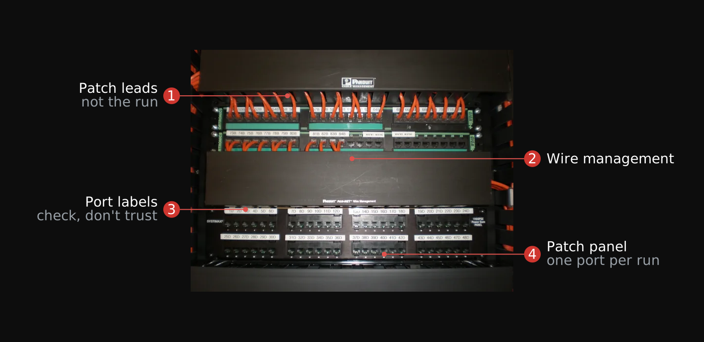
- Start at the communications closet. Structured cabling converges on one room per floor. The runs land on patch panels and punch-down blocks there, and the far end of each is a wall jack somewhere on that floor. This is the end you can see all of.
- Read the labelling, and distrust it. Panels are labelled by port and room at installation and are rarely updated afterwards. Treat a label as a lead to check, not as the identity of the run.
- Confirm the run is unpowered. Unplug it from whatever it lands on at the panel end. Nothing is sourcing power once the run is disconnected from live equipment, and Clause 33's handshake means an unconnected run has no voltage on it to begin with.8
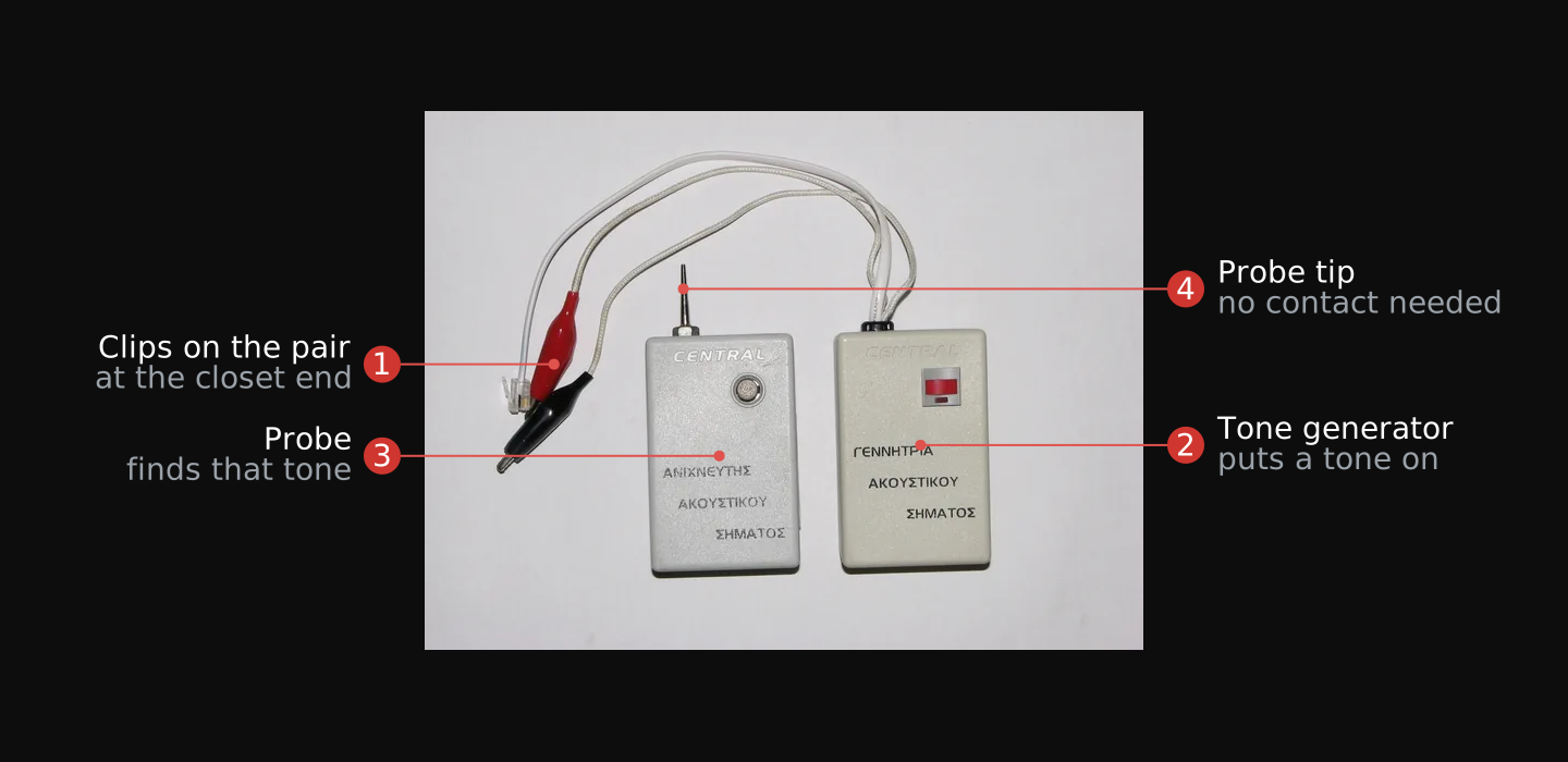
- Tone the run end to end. Put a tone generator on the pair at the closet and walk the floor with the probe until you find the same tone at a wall jack. That is what proves the cable at one end and the cable at the other are the same cable, and it is the only thing that does.
- Measure the length. Read the run length from a tester, or from the printed footage marks on the cable jacket at both ends. You need this number to know whether the run is inside the 100 m reach6 and to plan where Unit 02's remote site can sit.
- Read the category off the jacket. The jacket is printed with its category. Cat5e or better carries gigabit to 100 m; older Cat6 carries ten-gigabit only over a short run.7 This decides what rate to expect before you terminate anything.
- Inspect both ends for damage. Look at where the cable emerges from the wall at each end: crushed jacket, kinks, and cuts are where a reclaimed run fails. Note how much slack you have to cut back into good cable.
Verify: one run identified at both ends by tone, disconnected and unpowered, with its length, category, and end condition recorded.
Ownership is not in question for abandoned office ethernet: it is customer-side inside wiring, the same category the demarcation-point rule in Unit 07 places on the customer's side, and otherwise ordinary fixtures of the building.
Terminate and test the run
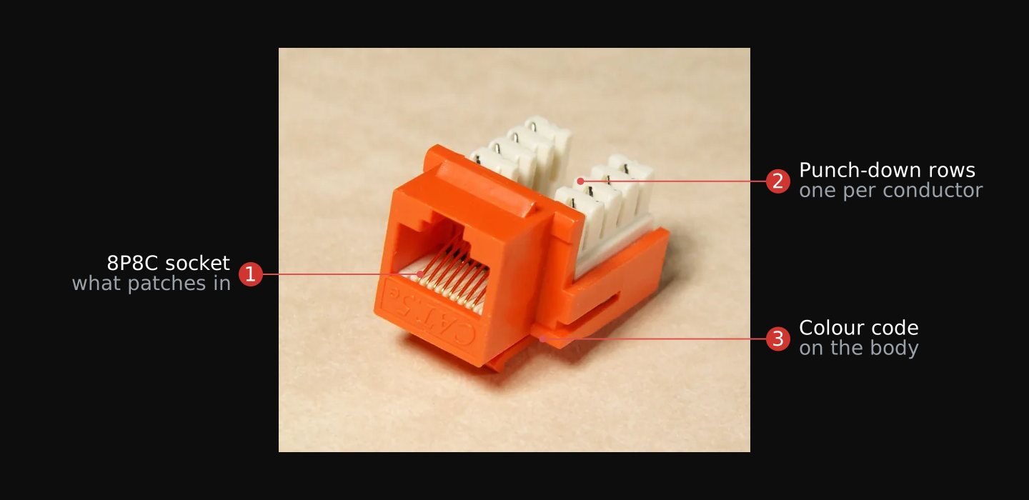
Terminate each end of the run you traced in Unit 05 on a keystone jack or an 8P8C plug, then test the whole path end to end before you connect anything to it. Both ends carry the same colour code and the tester reports all eight conductors correct, or the run is not finished. A termination fault that reaches service reads later as a link that negotiates low or drops under load, and by then the diagnosis costs you a walk to both ends of a 100 m run.6
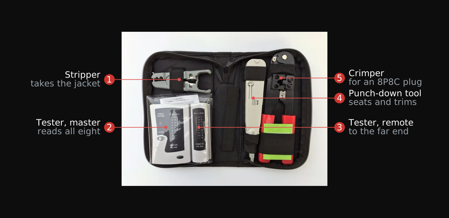
- Cut back to good cable at both ends. Remove the damaged length you found in Unit 05 and start from cable you can see is sound. Cutting back costs run length, which is why you measured it first.
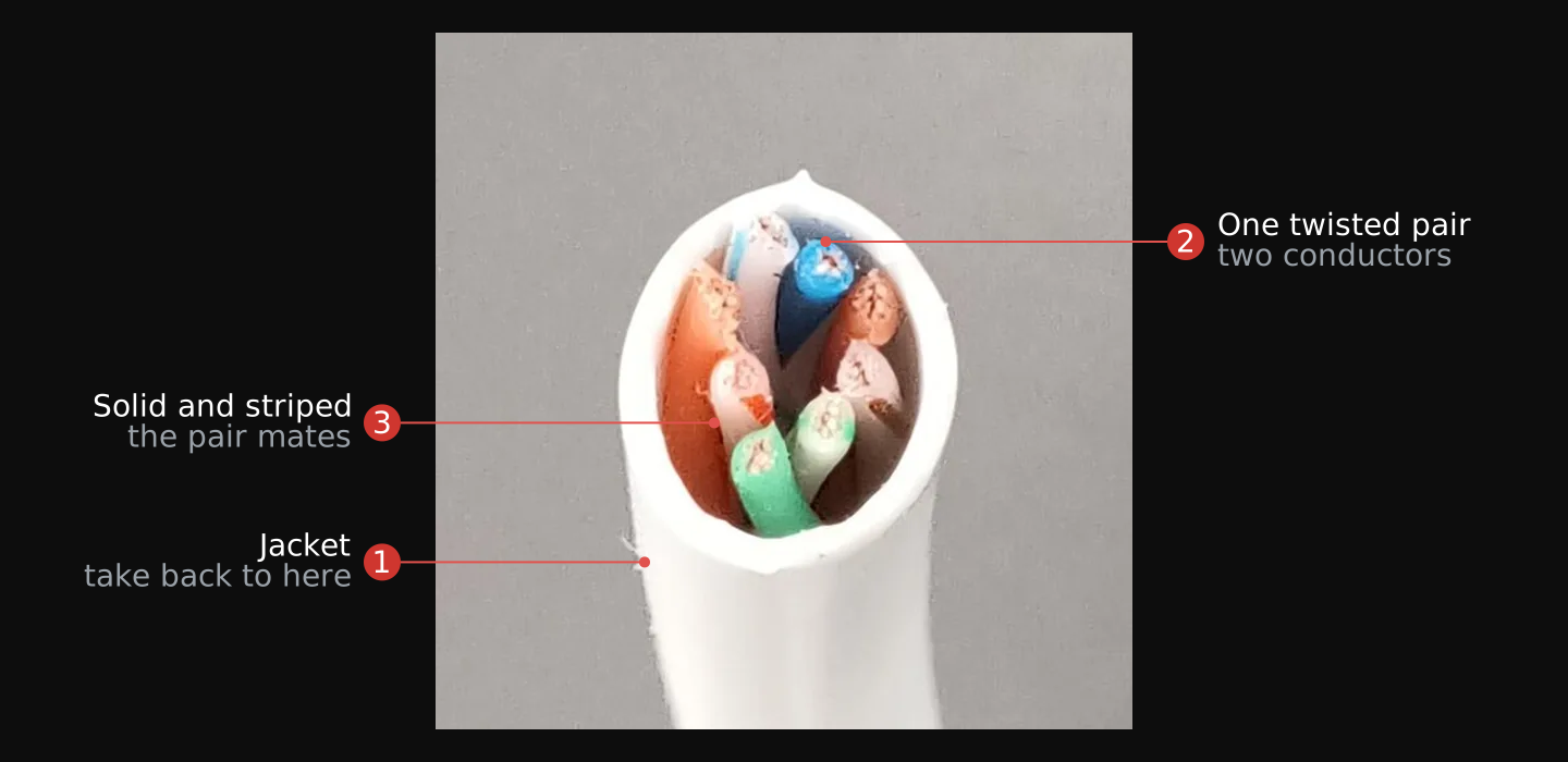
- Remove the jacket. The manufacturer procedure is to “Remove about 3 in. of cable jacket. If your cable includes a center spline (stiff wire separator inside cable), remove it also.”20
- Route the conductors to the colour code. Determine the wiring scheme, T568A or T568B, from the label on the jack, then “Leave the cable jacket within 1/8 in. of the jack side, then route the wires for termination using the color code” for the scheme you chose.20 Use the same scheme at both ends of the run: the two differ only in which pair sits where, and mixing them across the ends crosses pairs.
- Seat the conductors and trim. “Use your fingers to carefully seat the wires into the IDC slots. Set a 110-style impact tool to low impact and position it perpendicular to the jack. Maintain wire pair twisting to less than 1/2 in. of the IDC contact; then, seat and trim the cable.”20 That half-inch limit is the figure to work to: the twist is what rejects noise on the run, and it is given up only in the last half inch before the contact.
- Test the run end to end with a cable tester. The tester walks the eight conductors in order and reports opens, shorts, and pairs crossed between the two ends. This is the step that catches a termination fault while the tools are still in your hand.
- Bring the interface up and read the negotiated rate. Patch a node to each end, then confirm from the operating system that the link came up and at what speed. The negotiated rate is the run's own verdict on itself.
$ ip link show eth0
$ sudo ethtool eth0 # Speed: and Link detected: are the two lines that matter
- Measure what the run actually carries. A link that negotiated 1000 Mbit/s has agreed a rate, not demonstrated one. Run a throughput test between the two nodes and record the figure it returns, and record loss and latency alongside it.
$ iperf3 -s # on the node at the far end
$ iperf3 -c 192.168.1.10 -t 30 # on your node, against the far end's address
$ ping -c 100 192.168.1.10 # loss and latency across the reclaimed run
Verify: both ends terminated, a tester showing all eight conductors correct end to end, a negotiated link at the rate the category supports, and a recorded throughput figure with zero packet loss.
Find the demarcation point
Twisted-pair telephone wiring run for a service that is gone emits nothing, the same as the ethernet run. Unlike the ethernet run it carries a legal boundary and a safety step, and both come before you touch it. Find the boundary first. Unit 08 then proves the pair is dead and Unit 09 drives it, and neither is safe until you know which side of the boundary you are working on.
The legal boundary is the demarcation point. Telephone wiring divides into two sides at a spot the rules define. The demarcation point is “the point of demarcation and/or interconnection between the communications facilities of a provider of wireline telecommunications, and terminal equipment, protective apparatus or wiring at a subscriber's premises.”9 Everything on the subscriber's side of that point is customer-owned inside wiring; everything on the carrier's side belongs to the telephone company.
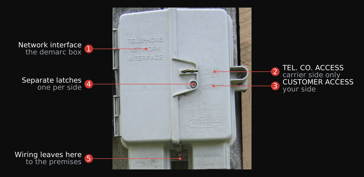
- Find where the telephone wire enters the building. Follow the drop from the pole or the buried service to the wall it lands on. The enclosure it lands in is the network interface, and it is almost always on an outside wall or in the first room the service reaches.
- Locate the protector inside that enclosure. The rule that places the demarcation point puts it, in a single-unit building, at “a point within 30 cm (12 in) of the protector or, where there is no protector, within 30 cm (12 in) of where the telephone wire enters the customer's premises.”10 That measurement is how you find the boundary when nothing is labelled.
- Read the lid. The enclosure is usually moulded with the boundary on it: one compartment marked for telephone company access and a separate compartment marked for customer access, closed by separate latches. Where those markings exist, they are the boundary drawn for you.
- Open only the customer side. The subscriber may install, remove, reconfigure, and rearrange wiring on the subscriber's side of the demarcation point, and may not access the carrier's wiring or the protector on the carrier's side.11 The carrier's latch stays shut.
- Trace your pair inward from that point. Everything running from the customer side into the building is the wiring you may work. Follow it to where it terminates inside the premises, and work only what you find on that side.
- Confirm the pair is yours to reclaim. Reclaim only a pair you installed or own. A pair on your own side of the demarc that belongs to somebody else's premises is not yours, and neither is a pair still carrying a service.
Verify: the demarcation point identified on the building, the customer side open and the carrier side untouched, and one candidate pair traced inward from it.
Prove the pair is dead
A pair you believe is dead may not be. A telephone pair can be energized, and a live pair is the carrier's, not your dead one. So the pair gets tested before it gets touched, in the same verify-the-meter, test-the-line, confirm-dead order a qualified person follows before working any circuit as de-energized.12 Run the six steps below in order. A pair that fails any one of them is not reclaimed.
- Prove the meter works on a known live source. Read a source you know is energized before you read the pair. A meter that is switched to the wrong function, or has a dead battery or a broken lead, reads zero on everything, and zero from a broken meter looks exactly like a dead pair.12
- Read the pair for AC voltage. With the meter proven, read across the two conductors of the candidate pair, then from each conductor to ground.
- Read the pair for DC voltage. Repeat both readings on the DC range. A telephone pair can carry voltage that the AC range alone does not show, so both ranges are read before any conclusion.
- Listen for dial tone. Put a butt set or a telephone across the pair. A dial tone is a live service, whatever the meter showed.
- Apply the rule. Any voltage on the pair, or a dial tone, means the line is live: it is not your dead pair. Stop, and walk away. Only a pair that reads dead on both ranges, with no dial tone, on your own side of the demarc, is one to reclaim.
- Prove the meter again on the known live source. Confirm the meter still reads correctly after the test. A meter that failed between the first check and the pair reading would have given you a dead reading on a live pair.12
Verify: a meter proven live before and after, zero volts AC and DC across the pair and to ground, and no dial tone.
Drive the pair
You are reclaiming the pathway, not the copper. Two wires cost almost nothing. What costs money and access is the route they take: through a wall, up a riser, between floors, across a courtyard to an outbuilding. Someone paid for that pull, and the conduit and the wall penetrations are still there. That is why a phone pair is worth reclaiming even though it carries less than the ethernet run in Unit 05, and it is why the phone pair is often the only path that exists between two points you want to link.
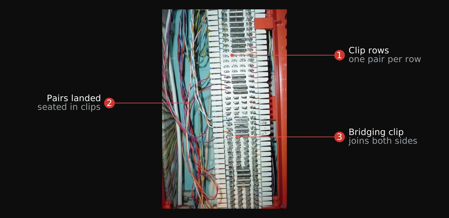
A single pair needs a line driver, because two wires alone are not an ethernet link. The line driver is a physical object you buy: a small converter with an ordinary RJ-45 ethernet jack on one side and a two-screw terminal on the other. One sits at each end of the reclaimed pair. Working devices ship today for exactly this: a single-pair ethernet media converter presents “10BASE-T: RJ-45” on one side and “10BASE-T1L: 2-Pin Terminal” on the other, runs “10Mbps fullduplex data rates,” is “Plug-and-Play” to install, and will “extend the Ethernet link distance up to 1km.”15 The standard behind it is single-pair ethernet, 10BASE-T1L (IEEE 802.3cg-2019): 10 Mbit/s full duplex over one balanced twisted pair, up to 1 km.13 Where a run is longer still, G.SHDSL, the symmetric DSL standard, carries up to about 5.7 Mbit/s on one pair and reaches roughly 3 km, trading rate for distance as the pair gets longer.14
- Identify the same pair at both ends. With the pair proven dead by Unit 08 and on your own side of the demarc, put a tone generator on it at one end and probe for that tone at the other. A tone generator and probe is the ordinary way to prove that the two wires you have in one room are the two wires you have in the other, and on a cable carrying twenty-five pairs it is the only way.
- Choose the converter to the run length. Under 1 km, a 10BASE-T1L converter gives 10 Mbit/s full duplex.13 Past that, G.SHDSL gear reaches roughly 3 km at up to about 5.7 Mbit/s.14 Measure the run before you buy the pair of converters, because they must match at both ends.
- Land the two conductors on the converter at each end. Strip the two conductors of that one pair and seat them on the two-pin terminal of a converter at each end of the run. Nothing else from the cable is used; the other pairs stay where they are.
- Power both converters and confirm the link. Each converter needs its own supply at its own end. The link indicator on both converters is the first observable result: two ends lit means the pair is carrying.
- Patch each end over ordinary ethernet. Run a normal ethernet patch cable from each converter's RJ-45 jack to whatever sits at that end. From either side the reclaimed pair is invisible: what each end has is an ethernet interface.
- Test the link as a link. Bring the interfaces up and measure across the pair the same way Unit 06 measured the ethernet run. Record the rate the pair actually delivers, with its loss and latency.
$ ip link show eth0 # the converter presents an ordinary ethernet interface
$ iperf3 -c 192.168.1.10 -t 30 # what the driven pair actually carries
$ ping -c 100 192.168.1.10
Verify: link indicators lit on both converters, an ethernet interface up at each end, and a measured rate and loss figure across the reclaimed pair.
The old pair carries a current standard. Twisted pair pulled decades ago for analog voice, engineered for a few kilohertz of speech, carries a standard ratified in 2019 at 10 Mbit/s and ten times the reach modern Cat6 manages. The pair was always better than the service riding it; what changed is the silicon on each end. You are not nursing obsolete equipment along. You are putting current hardware on a path somebody else paid to install, and getting reach that new cabling cannot match.
Reticulum runs over this link, because it never sees the phone pair at all. The converters present a standard ethernet interface at each end, so what Reticulum is offered is ethernet. Its AutoInterface “enables communication with other discoverable Reticulum nodes over any kind of local Ethernet or WiFi-based medium,” and the manual states the condition plainly: as long as some switching medium is present between peers, “a wired switch, a hub, a WiFi access point or similar, or simply two devices connected directly by Ethernet cable,” it “will work without any configuration, setup or intermediary devices.”16 Two nodes joined by converters over a reclaimed pair are two devices connected directly by ethernet. AutoInterface discovers peers using link-local IPv6 and carries packets over UDP, so it needs link-local IPv6 support on each node;16 where that is unavailable, the TCP interfaces do the same job over “private IPv4 and IPv6 networks” with a fixed address and port at each end.16 How to configure and run Reticulum is Module 09. The bearer it needs is the one you just built.
Connect the terminal to the bearer
You have a bearer: a dish link from Units 03 and 04, a terminated ethernet run from Units 05 and 06, or a driven pair from Units 07 to 09. Connect it to the terminal you sited in Unit 02. The six steps run the same way for all three bearers; only step 3, the hand-off at the far end, differs by bearer.
- Site the whole kit at the far end. Put the terminal at the site you chose in Unit 02, with its own power there. For the Standard kit that means the dish and Router 3 together, because the “Starlink Cable 15 m (49.2 ft)” is a fixed length between those two and is not the thing you extend.17 For the Mini it is the one unit.18
- Bring the terminal up on its own. Confirm it has a connection at the remote site before any of your bearer is attached. A terminal that will not connect there is a site problem, and finding that after the bearer is built costs you the trip twice.
- Connect the ethernet port to the bearer. Run a patch lead from the terminal's ethernet LAN port, one on the Mini18 or one of Router 3's two,17 into the far end of the bearer. Dish path: into the radio feeding the repurposed dish at that end. Ethernet path: into the jack you terminated at that end, keeping the whole run inside the 100 m reach.6 Phone-pair path: into the RJ-45 jack of the converter at that end.
- Patch your node to the near end. At your position, connect your node to the other end of the bearer: the radio and second dish, the terminated jack, or the near converter. Your node comes up on the network the remoted terminal serves.
- Confirm traffic crosses the whole path. Reach the internet from your node, through the bearer, through the terminal at the far site. Then measure it, so the figure you record is what the whole path delivers rather than what the bearer alone did in its own unit.
- Sweep your own position with a receiver. With the link up and carrying traffic, check your own position for emissions. This is the result the whole module is built to produce, and it is the one step that cannot be inferred from the others.
$ ping -c 20 1.1.1.1 # through the bearer, through the terminal at the far site
$ curl -o /dev/null -w "%{speed_download}\n" https://speed.cloudflare.com/__down?bytes=100000000
Verify: your node reaches the internet through the terminal at the far site, with a recorded rate across the whole path, and a receiver at your own position finds nothing radiating there.
Emissions and signature
The three salvaged bearers were chosen for the same property: each gives a listener little or nothing to find. One scale ranks all three, so the bearer you choose in the field exercise is a deliberate choice rather than whatever you found first.
The signature of a bearer is how findable it is by someone looking. A radiating transmitter is findable because the signal that reaches your correspondent also reaches everyone else with a receiver. A signature-management guide puts it plainly: “strong signals travel farther…all the way to the adversary's DF receivers.”3 Direction finding, the skill Module 06 and Module 07 read from the other side, works on exactly that: an emission that is on the air can be located. Reducing a signature is therefore an emission problem, and the same guide names the two levers, “reducing power and using directional antennas to limit signatures.”3
The wired bearers pull the emission to nothing. A reclaimed ethernet run or phone pair carries its signal as a voltage conducted along the copper, not as a wave launched from an antenna. There is no transmitter on the air to find, which is the reason the same guide directs units to fall back on wire in a fixed position and records that forces under near-continuous jamming “have learned to depend on wire communications in stationary positions.”3 A conducted link between two points you own is the quietest bearer in this module: it does not radiate, so direction finding has nothing to work on.
The dish pulls the emission into a narrow beam. The repurposed dish does radiate, but Unit 04 aimed its energy into a cone only a few degrees wide, which is the directional-antenna lever the guide names. A listener off the beam axis receives a small fraction of the power, so the link that closes to your correspondent is hard to intercept from the side. It is not silent like the wire, but it is far quieter than an omnidirectional radio putting the same power in every direction.
The emitter is not the problem; its position is. Unit 02 established that a Starlink terminal “continuously emits a radio signal” whenever it is connected.1 That emission has to happen somewhere for the capability to exist at all. What the reclaimed bearers let you decide is where. Put the terminal at a site you can afford to have found, carry its traffic back over wire that radiates nothing or a beam only a few degrees wide, and the capability arrives at a position that gave a listener nothing. Capable and quiet is that separation: keep the modern kit, and put what it broadcasts somewhere other than where you are.
On your own site, the emission you accept is the one you placed deliberately, at a distance and behind cover, and everything else on your position is conducted. What a listener finds then is a terminal on somebody else's roof and a reclaimed pair in a wall that was there before you arrived.
Field exercise
Task: Site an emitter away from your position and reach it over reclaimed infrastructure, proving the link carries traffic while your own position radiates nothing. Site the emitter (a Starlink or cellular terminal, or any transmitter you are licensed to operate) at a separate location, build the path back on one reclaimed bearer (a repurposed dish link, a reclaimed ethernet run, or a reclaimed phone pair), and pass real traffic across it. Work only on your own side of any demarcation point, and reclaim only wiring you installed or own. Never open or connect to the carrier side of a demarc.
Condition: Given an emitter you own and may lawfully operate, with power and a site to put it on; the reclaimed bearer (a salvaged dish with a feed cut for a license-free band, an abandoned Cat5e or Cat6 run, or a phone pair you installed or own and have confirmed dead); your node at the near end; the gear to build and confirm the path (for the dish, mounts, a compass, and a receiver that shows a signal reading; for ethernet, termination tools and a tester; for a phone pair, a meter, single-pair converters, and a tester); and a receiver to check your own position for emissions.
Standard: The product is a dated record of an emitter sited away from your position and reached over reclaimed infrastructure. It states where the emitter was sited, how far it stands from your position and what lies between them; the hardware reclaimed; the link parameters for the bearer you built (for the dish, the derated gain and the final azimuth and elevation; for ethernet, the run length and the negotiated rate; for the phone pair, the pair confirmed dead and the converter rate); and the traffic delivered across the link, a file transferred or a connection held, with its size or duration. The link is Quiet at your end: with it up and carrying traffic, a receiver at your own position finds nothing radiating there, because the emission is at the far site. All work stayed on your own side of any demarcation point. (The resilience demonstration, cutting a bought bearer and watching the link survive, is Module 09's capstone, which rides this link.) The ethernet and dish paths are buildable now; the phone-pair path is buildable once you have confirmed the pair is dead by the test-before-touch rule of Unit 08.
Download the field exercise worksheet (PDF)
Decide where your emissions happen before you need the capability, not after. Site the emitter where being found costs you little, reach it on a path the building already contains, and keep your own position conducted and quiet. When Module 09's network runs over these bearers, the physical path is already built and already known to work.
Module test
Task: Complete the Module 08 test.
Condition: Given ten questions covering units one through eleven, without reference to the module units or notes.
Standard: Answer at least eight of ten questions correctly. For each question missed, reread the unit named in the feedback and retake the test until the standard is met.
Glossary
- Aperture efficiency
- The fraction of a dish's physical area converted into gain. References put a parabolic antenna near 0.5; measured reclaimed field dishes run 0.1 to 0.5, which is why a published gain is a ceiling.
- Bearer
- The physical path a signal travels between two points, a stretch of radio or a run of wire. Distinct from the network, the addressing and routing that runs over it.
- Cat5e / Cat6 / Cat6a
- Categories of twisted-pair structured cabling. Cat5e carries gigabit ethernet to 100 m; Cat6a carries ten-gigabit to 100 m; older Cat6 carries ten-gigabit only over a shortened distance.
- Demarcation point
- The point that divides a telephone provider's facilities from the subscriber's inside wiring. Work stays on the subscriber's side; the carrier's side and the protector are off limits.
- Feed
- The small resonant antenna at a dish's focus. It sets the operating band; the reflector is nonresonant geometry.
- Line driver
- A device that turns a single wire pair into a data path, such as single-pair ethernet (10BASE-T1L) or DSL. A dead phone pair needs one to carry data.
- Power over Ethernet
- Optional power carried on an ethernet run, applied only after the sourcing equipment and the powered device complete a detection handshake. An unpowered run carries no voltage.
- Protector
- The telephone company's device on the carrier side of the demarcation point. Off limits; never opened or connected to.
- Reflector
- The parabolic surface of a dish. It is nonresonant, so it works over a wide range of frequencies; the feed at its focus decides the band.
- Sidelobe
- A smaller off-axis lobe of a directional antenna's pattern. It can read like a signal while delivering a fraction of the gain, which the overshoot-and-return aiming check rules out.
- Signature
- How findable a bearer is by someone looking. A radiating transmitter has one; a conducted wired bearer has effectively none.
Sources
- Scientific Center for Communications and Informatization, Heroes of Kruty Military Institute of Telecommunications and Informatization (Armed Forces of Ukraine), Methodological Recommendations on Protecting Starlink Satellite-Communication Terminals from Enemy Electronic-Influence Assets (order of 01.05.2023 No. 308/98/4671). Light Fighter Library, Communicate/SATCOM; translated from Russian. The terminal as a continuously emitting radio link subject to detection and suppression; onboard GPS receiver and self-positioning; narrow vertical beam versus horizontal-plane EW; cold-start vulnerability and the first-activation caution; foreign-operator hardware and software “provided for use”; programmatic GPS-disable as a protection method.
- Marc Lichtman, Roger Piqueras Jover, Mina Labib, Raghunandan Rao, Vuk Marojevic, and Jeffrey H. Reed, “LTE/LTE-A Jamming, Spoofing, and Sniffing: Threat Assessment and Mitigation” (Virginia Tech; Bloomberg LP). Light Fighter Library, Communicate/Cellular-5G. The sparse control-channel structure that makes LTE “vulnerable to efficient jamming.”
- “Signature Management EPEMCON SOP: A Guide to Reduce Technical Signature” (Light Fighter Library, Communicate/EW-SIGINT). The WIRE method (communicate between stationary positions with comm wire and field phones); the note that Ukrainian forces under near-continuous jamming have learned to depend on wire communications in stationary positions; reduce-power and directional-antenna doctrine.
- U.S. Marine Corps, MCRP 8-10B.11 Antenna Handbook (Light Fighter Library, Communicate/Antennas). Directional-antenna aiming: for a narrow-beam antenna “great accuracy is required to determine azimuth”; unless a line of known azimuth is on site, “the direction of the path is best determined by a magnetic compass,” corrected for magnetic declination. US Government work, public domain.
- SCCo ARES/RACES, “WiFi Antenna Alignment,” scc-ares-races.org (accessed 2026-08-11; capture in Light Fighter Library, Communicate/Antennas). Fine-aiming a directional/dish antenna on a signal-strength reading: swing to the azimuth, sweep “a degree at a time” and pause, go “very slowly at first or you will move right past the signal”; the overshoot-and-return check (“keep going past it by a few degrees to verify that the signal level decreases,” then “come back to the maximum signal”); half-degree refinement of azimuth then elevation (“usually this is only needed with very high gain antennas”); locking the mount while monitoring the reading (“it's not unusual for the antenna to move while you tighten the clamps”).
- IEEE Std 802.3 (Ethernet). 1000BASE-T gigabit ethernet over four pairs of Category 5e to 100 m (Clause 40, IEEE 802.3ab); 10GBASE-T ten-gigabit ethernet over Category 6A to 100 m (Clause 55, IEEE 802.3an). Reach and rate stated per IEEE 802.3; corroborated by manufacturer and standards summaries. The free IEEE 802.3-2022 primary (IEEE GET Program, account-gated) was not read in full for a verbatim clause citation.
- TIA-155-A (successor to TSB-155), Additional Guidelines for 4-Pair 100 Ω Category 6 Cabling for 10GBASE-T Applications; the reduced 10GBASE-T reach on installed Category 6 (roughly 37–55 m depending on bundling) is an alien-crosstalk cabling guideline from TIA, not an IEEE 802.3 clause. Cross-checked against 10GBASE-T, Wikipedia, en.wikipedia.org/wiki/10GBASE-T (“Category 6 cables can carry 10GBASE-T for shorter distances when qualified according to the guidelines in ISO TR 24750 or TIA-155-A”; accessed 2026-08-11). The ANSI/TIA-568 100 m channel definition (90 m link plus 10 m patch) is paywalled and not reproduced here.
- IEEE Std 802.3, Clause 33, Power over Ethernet (DTE Power via MDI; 802.3af/at/bt). Power is optional and negotiated: the power sourcing equipment (PSE) and powered device (PD) complete a detection handshake before any power is applied to the pairs. Corroborated by the Ethernet Alliance PoE overview. POTS talk/ring voltages are deliberately not used as a comparator here (see Unit 05; those figures are held pending a primary).
- 47 CFR § 68.3, “Definitions” (Demarcation point), via the Cornell Legal Information Institute, law.cornell.edu/cfr/text/47/68.3 (accessed 2026-08-11). “Demarcation point. The point of demarcation and/or interconnection between the communications facilities of a provider of wireline telecommunications, and terminal equipment, protective apparatus or wiring at a subscriber's premises.”
- 47 CFR § 68.105, “Minimum point of entry (MPOE) and demarcation point,” via the Cornell Legal Information Institute, law.cornell.edu/cfr/text/47/68.105 (accessed 2026-08-11). The single-unit demarcation point at “a point within 30 cm (12 in) of the protector or, where there is no protector, within 30 cm (12 in) of where the telephone wire enters the customer's premises, or as close thereto as practicable.”
- 47 CFR § 68.213, “Installation of other than fully protected non-system simple customer premises wiring,” via the Cornell Legal Information Institute, law.cornell.edu/cfr/text/47/68.213 (accessed 2026-08-11). The subscriber and/or premises owner may install, remove, reconfigure and rearrange wiring on the subscriber's side of the demarcation point, and may not access the carrier's wiring, facilities, or the installed protector on the carrier's side.
- 29 CFR § 1910.333(b), “Working on or near exposed deenergized parts” (verification of a deenergized condition), via the Cornell Legal Information Institute, law.cornell.edu/cfr/text/29/1910.333 (accessed 2026-08-11). A qualified person uses test equipment to test the circuit elements and parts to which employees will be exposed and verifies they are deenergized. Cited here by analogy for the test-before-touch principle; the standard's strict instrument-recheck step applies to circuits over 600 volts, nominal.
- IEEE Std 802.3cg-2019, 10BASE-T1L single-pair ethernet: 10 Mbit/s full duplex over a single balanced twisted pair, reach up to 1 km. Corroborated by Ethernet over twisted pair, Wikipedia, en.wikipedia.org (accessed 2026-08-11).
- ITU-T G.991.2 (G.SHDSL), symmetric single-pair DSL: data rates up to 5,696 kbit/s on one pair (extended mode) and reach up to roughly 3,000 m, trading rate for distance. Per Single-pair high-speed digital subscriber line, Wikipedia, en.wikipedia.org (accessed 2026-08-11).
- Omnitron Systems, OmniConverter 10T/T1L, 10BASE-T to 10BASE-T1L Single-Pair Ethernet (SPE) Media Converter, omnitron-systems.com (accessed 2026-08-11; capture in Light Fighter Library, Communicate/Networking). Ports “10BASE-T: RJ-45” and “10BASE-T1L: 2-Pin Terminal or IEC 63171-2 SPE connector”; “10Mbps fullduplex data rates”; “Plug-and-Play installation”; “extend the Ethernet link distance up to 1km.” Manufacturer datasheet, cited as one commercially available example of the line-driver device class; equivalents are made by Altronix and WAGO among others.
- SpaceX, Starlink Standard 4X Specification Sheet, starlink.com (accessed 2026-08-11; copy in Light Fighter Library, Communicate/SATCOM, with fulltext). Kit contents including “Router 3” and “Starlink Cable 15 m (49.2 ft)”; Router 3 “Ethernet Ports: Two (2) Latching Ethernet LAN ports with removable cover”; “Power Consumption Average: 75 - 100 W.” Manufacturer specification for the current Standard kit.
- SpaceX, Starlink Mini Specification Sheet, starlink.com (accessed 2026-08-11; copy in Light Fighter Library, Communicate/SATCOM, with fulltext). “Starlink with Integrated WiFi”; weight 1.10 kg (1.53 kg with kickstand and 15 m cable); “Power Consumption Average: 25-40W”; “Input Rating 12-48V 60W”; “Ethernet Ports: One (1) Latching Ethernet LAN port with Starlink Plug”; “IP67 Type 4 with DC Power Cable and Starlink Plug/Cable installed” and the note “This product is no longer rated IP67 with a standard RJ45 cable.” Manufacturer specification for the current Mini kit.
- Leviton, Installation Instructions: LEVITON eXtreme Cat 6 and Cat 5e Jacks for the QuickPort Connector Product Line, PK-93268-10-02-0K-W, leviton.com (accessed 2026-08-11; copy in Light Fighter Library, Communicate/Cabling). Manufacturer termination procedure for a keystone jack: jacket removal, jacket-to-jack distance, seating the conductors, impact-tool setting, and the pair-twist limit at the contact.
- SpaceX, “What is bypass mode?”, Starlink Help Center, starlink.com (accessed 2026-08-11). Manufacturer documentation for the setting that disables the built-in router's WiFi so a third-party router runs the network. The support site renders its article bodies in JavaScript and neither the live page nor its archived snapshot returns readable text to a fetch, so this module states the mechanism without quoting it. Verify the current wording and the app menu path against the article before relying on the step.
- Reticulum Network Stack manual, “Supported Interfaces,” reticulum.network/manual/interfaces.html (accessed 2026-08-11; capture in Light Fighter Library, Communicate/Networking). AutoInterface over “any kind of local Ethernet or WiFi-based medium” and its no-configuration condition; link-local IPv6 discovery with UDP transport; the TCP server and client interfaces over “private IPv4 and IPv6 networks.” Cited here only to establish that the reclaimed bearer is fit; Reticulum itself is taught in Module 09.