On this page
Batteries and power
Every build in this module runs on a battery, so the module begins with what a battery is. The basic unit is the cell: "two electrodes made of different types of metals or metallic compounds placed in an electrolyte solution."16 A battery, strictly speaking, is "a group of two or more connected voltaic cells,"16 though in everyday use the word covers both. The voltage comes from chemistry. One electrode gives up electrons and turns negative, the other turns positive, and that difference lets the cell act "as a source of applied voltage."16 A car battery is a wet cell, with liquid electrolyte inside; the cells in your builds are dry cells, where "the electrolyte is a paste."16 A cell you use once and throw away is a primary cell, and one you can recharge is a secondary cell.16
A cell carries two ratings that matter here. The first pair is its voltage, which is how hard it pushes, and its capacity in milliamp-hours, which is how much charge it holds. The arithmetic between them is simple. A 3000 mAh cell "can supply 3000 mA for one hour. Or, alternatively, 3A for an hour."1 Divide the capacity by the current your circuit draws and you have an estimate of the runtime: "if your project only uses 30mA, you can expect the battery to last 100 hours (3000/30)."1 Treat that as a rule of thumb rather than a promise, because the harder you draw, the less of the rated capacity you actually get; under practical load a real battery returns "only about 20 to 30 percent of the theoretical capacity."17 The second rating is the C-rate, and it sets how hard you may pull at all. One C means draining the whole capacity in one hour, so "a battery cell with a rated capacity of 2 Ah and a maximum continuous discharge current of 4 A has a C rate of 2."18 Pull past the rating and the cell overheats, "sometimes 'on fire' hot."1 The calculator below does the runtime arithmetic for you.
The voltage printed on the label is not what you get under load, and the reason is internal resistance. A meter across a fresh cell reads its full voltage, but the moment current flows, "the internal voltage drop... drops the terminal voltage of the battery."16 A fresh 1.5-volt AA "will be about 1.5V and will quickly fall to about 1.3V under load but still deliver useful amounts of power down to about 1V," which means a four-cell pack can sit anywhere between 6 and 4 volts.1 A 9-volt battery behaves the same way and "will deliver between 7 and 10 volts," depending on its chemistry and its wear.8 Lithium cells sag the same way: "This drop in voltage is known as voltage sag."18 On an RC LiPo you watch the sag closely, because the cell "should never drop below 3.0V while in use."18
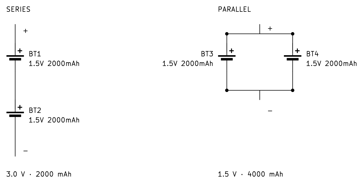
Cells combine in two ways. Wire them in series, positive to negative, and the voltages add while the current stays the same: "four 1.5V cells provide a total of 6 volts."16 What does not add is capacity, so "if you put four 1.5V batteries in series, the capacity would still be 2000mAh, but at 6V rather than 1.5V."1 Pack builders count the series cells as the S number, and the pack's voltage is the cell's nominal voltage times that count.18 Parallel is the mirror image: the voltage stays the same and the capacities add.16 It comes with one hard rule. Match the cells before you join them, because "before you connect any battery cells... in parallel, you MUST ensure that they have nearly identical voltages," or the fuller cell "will try to dump a large amount of energy at once into the lower charged cell," and that can end in fire.18
Each chemistry is a trade-off. Alkaline cells are cheap, hold 1.5 volts, and keep their charge for years, losing only about 4 percent of it annually, but they are primary cells and go in the trash when they are flat.17 NiMH rechargeables store more energy, about 75 watt-hours per kilogram, but they leak it quickly, self-discharging at 15 to 25 percent a month.17 Lead-acid is heavy and stores little for its weight, about 35 Wh/kg, but it is "the most robust of the technologies, offering the least chance of fire or explosion," which is why it still starts cars.1 Lithium-ion, including its soft-pouch form, stores the most by far, about 150 Wh/kg at 3.6 volts nominal and 4.2 volts full, and survives more than a thousand charge cycles.17 That density is why a lithium cell powers a Raspberry Pi or an FPV pack in the field, and it is also why lithium is the chemistry you handle with the most care. A Pi wants a steady 5 volts and a sensor often wants 3.3, so a single lithium cell feeds a regulator or a boost converter rather than the board directly.
One term needs a correction before you shop for cells. True lithium-polymer never left the laboratory; what the market sells as "LiPo" is a lithium-ion cell packed in a soft pouch.18 The high-discharge "RC LiPo" flown in drones is a specific cobalt chemistry, and Toll is blunt about it: these "are the dangerous ones... itching to burn your house down if you don't follow proper charging and discharging procedures."18
Charging a lithium cell takes more than applying voltage. A proper charger runs in two phases, constant current and then constant voltage,18 and it works by pushing a steady current until "the battery voltage reached the 4.2 V voltage limit,"17 then holding that voltage while the current tapers off. In practice that means a charger set to "4.2V and the current limited (usually to 0.5A),"1 and it means charging slowly, since "it is recommended not to charge most lithium cells at more than 0.5 C."18 The TP4056 board you meet in Build 2 is a single-cell charger that runs this whole sequence for you.
In the field, the charger's supply can be a solar panel, but a panel never runs your circuit directly. Its voltage reads high in open sun and "drops rapidly" the moment it is loaded, so the panel charges a battery and the battery runs the load.1 Size the panel to the battery it charges, not to the device the battery runs.
The next module is about salvage, and batteries are the most useful find, because dead laptops, power banks, and power tools are full of reusable 18650 lithium cells.19 A salvaged cell arrives with three unknowns, since you cannot see its quality, its remaining capacity, or its remaining cycle life from the outside. Each one has to be tested and then used gently, and the working rule is to "build a larger capacity battery than you think you'll need in order to draw less current from each salvaged cell."18 Opening the pack is the dangerous part. Work so that "only one side of the cell should be touching the metal tools at a time," never pull a welded strip off a cell, and discard any cell that is dented or that loses voltage just sitting on the shelf.19 The full teardown, test, and rebuild belongs to the salvage module.
Prototype, then make it permanent
Every build in this module takes the same path: you draw the circuit, you prototype it on a breadboard, and only when it works do you make it permanent. The order matters. A breadboard prototype is cheap and reversible, so the prototype stage is where you are allowed to be wrong. Solder is neither cheap nor reversible, so committing a circuit to solder comes last.
Draw it. Every build starts as a KiCad schematic, drawn on the laptop you hardened in Module 00, with the same symbols you learned to read in Module 02. The drawing is itself the first test, because KiCad's electrical-rules check performs "automatic detection of incorrect and missing connections"10 and will flag an unconnected pin, or a power input "not driven by any Output Power pins,"10 before you have picked up a single part. KiCad can go further and lay out a printed circuit board for fabrication, but that is beyond this course. Here, the schematic is the map you build from.
Watch the method on Build 1's own schematic in the walkthrough below. Each stage is the real drawing exported from KiCad, and the ERC report is the tool's verbatim answer.
Prototype it. A solderless breadboard lets you assemble a circuit with no soldering at all, so you can try a design "before you commit them to solder."1 Beneath its holes sit short metal rows called terminal strips, and "any two wires or leads connected to the same terminal strip are themselves connected."8 A gap called the bridge runs down the middle and splits the two halves, so that a chip can straddle it and "each leg of the chip will receive its own terminal strip."8 Along each edge run the power rails, "one with a red line and one with a blue line,"8 which carry the supply the length of the board. To build on one, place the real parts so that the connections match the schematic node for node, then prove it with the multimeter in two passes. Before power, set the meter to continuity and walk the drawing: every pair of points the schematic joins should tone, and separate nets should stay silent. Under power, set it to DC volts, put the black probe on ground, and read each node where the drawing predicts a value. The build is proven when the readings match the drawing. Each build's "Prove it" step names its own readings. One caution: give each leg of a part its own strip, because putting both legs into one strip shorts the part out.8
Make it permanent. A breadboard is temporary. As Monk puts it, the board "is very useful for trying things out, but not so useful as a permanent home for your electronics. The problem is that the wires tend to fall out after a while."1 Once the circuit works, you "transfer it to a more permanent home"1 on perfboard or stripboard, "a perforated board with conductive strips running underneath, rather like breadboard,"1 cut to size, with the parts soldered on. Such a board suits the job "because it has lots of holes with pads on which to solder."2 The new layout does not need to look like the drawing. In Monk's own build the parts end up "in rather different places"1 than the schematic, and that is fine, because what must match is the connections, never the positions. Soldering that board down is the next unit's subject.
A finished board still maps back to its drawing. The component side carries a legend "showing the placement of the parts and their schematic marking (R1, R2, etc.),"12 and reference designators such as CR1 for a diode tie each physical part to its symbol.11 When you repair the board a year later, "the schematic becomes the 'road map' and the top legend becomes the 'address' on the part."12
Soldering
Unit 2 left the working circuit on the breadboard; this unit commits it to solder. Solder itself is a filler metal "that is melted and flowed into a solder joint... to form a mechanical and electrically conductive connection."2 The other half of the chemistry is flux, a cleaner that works on the metal as the joint heats: "without flux or enough flux, the solder will not be able to bond properly in a process called wetting."2 Electronics solder saves you a step by carrying its flux in its own core.
There are two families of solder. Leaded 63/37 tin-lead melts at a low temperature and flows easily, which makes it the better one to learn on. Lead-free solder is mostly tin and melts hotter, "which makes it slightly more difficult to work with."9 Either way, set a through-hole iron in the 330 to 350 °C range for leaded work, and run lead-free a little hotter.915 Resist the urge to go higher than that. A bigger number does not make a better joint, because the joint's own mass governs how fast heat moves into it, and a tip run at its maximum only oxidizes faster.2
The motion is the same for every joint. You heat the joint itself, both the pad and the lead, and you feed the solder to the joint rather than to the iron. Adafruit describes what you should see: the solder "should melt and flow smoothly onto both the pin and the pad. If the solder does not flow, heat the joint for another second or two and try again."3 Heating the whole joint first matters, because "only after the whole joint has risen in temperature can solder be melted onto it."9 Guides differ on the fine timing. Adafruit heats first and feeds second, while SRA brings the heat and the solder in together to speed the transfer and reduce the chance of overheating; either method works once you can watch solder flow.2 A thin coat of solder on the tip, called tinning, is what carries the heat across quickly. Never file or sand a tip to clean it, because that strips the plating and ruins it.9
You can judge every joint by eye. A good joint is "smooth and slightly concave, quite shiny, not dull or crystalline-looking nor ball-bearing shaped."9 A cold joint, the most common beginner fault, is one "where the solder did not melt completely"; it looks rough and lumpy, and the cure is to reheat it until the solder flows.3 A disturbed joint has a frosted, crystalline look, because it moved while the solder was solidifying.3 An overheated joint shows burnt flux and a scorched board, and at its worst it lifts the copper pad clean off.3 The last faults come from quantity rather than heat. Too little solder leaves a "solder starved" joint that may touch today and fail later, and too much builds a blob that never wets into a clean cone. Worst of all is the solder bridge, where "two solder joints have melted together, forming an unintended connection" that shorts the pins.3
Much of this module's soldering is not a component in a hole. It is a wire onto a pad: the battery lead onto the TP4056 board, the siren's wires onto their supply, a header onto a bare board. The method is to tin each side before you join them: tin the pad into a bead, tin the stripped wire, and then melt the bead and sink the wire into it.1314 Match the heat to the metal. Small pads and thin signal wires run cooler than a board joint, about 310 to 330 °C, while a heavy pad drains heat into its copper and needs more: 400 to 450 °C, a wider tip, and a bigger iron.1314 What never works is a long dwell at any temperature, which can cook the pad off the board.14
Fixing mistakes is part of the skill, and so is salvage, because the parts, connectors, and chips you need for the next build are sitting on dead boards if you can lift them off cleanly. The object, in SRA's words, is to get the solder in a joint molten fast enough to draw it out "without damaging anything."2 Copper braid, pressed dry over the joint with the flat of a hot tip, wicks the solder up and out; a spring-loaded sucker melts the joint and vacuums it clear. The rules for lifting a part are strict. Clear one joint at a time, and never pull against solder that has not fully melted, or the pad and its trace come off with the part.2 Do not press braid straight down and hold it there, because the heat loosens the pad's glue.13 If a hole refuses to clear, add fresh solder to remelt the whole joint and ease the part out with pliers from the far side; dense surface-mount chips want hot air, not a sucker.2 And before you open any mains device, kill the power and drain the large capacitors, which hold a shock long after the plug is pulled.2
Build 1: power MOSFET switch
The first build solves a basic problem: a small control signal has to switch a load far heavier than it can drive. A logic pin supplies a few milliamps; a motor or lamp wants amps. The answer is a power MOSFET, a transistor used as a switch. As Monk notes, MOSFETs "are controlled by voltage rather than current and make very good switches," turning on when the gate voltage passes a threshold, "usually about 2V."1
The part here is the FQP30N06L, which Monk lists as a 30 amp N-channel MOSFET with a 2.0 volt gate threshold1 (its datasheet gives the threshold as a 1.0 to 2.5 volt window).5 It is a logic-level MOSFET, meaning its "gate voltage is low enough to be controlled directly by digital output pins on a microcontroller."1
In this build you make a knob that turns a DC motor from off to full speed, with the battery doing the work while the control side draws almost nothing. Monk's circuit runs on a 6 volt (4×AA) pack, and we use a 9 volt block to match the supply standard for these builds. A 10k trimmer potentiometer sets the gate voltage, the FQP30N06L switches the current, a DC motor is the load, and a 1N4001 flyback diode sits across the motor.
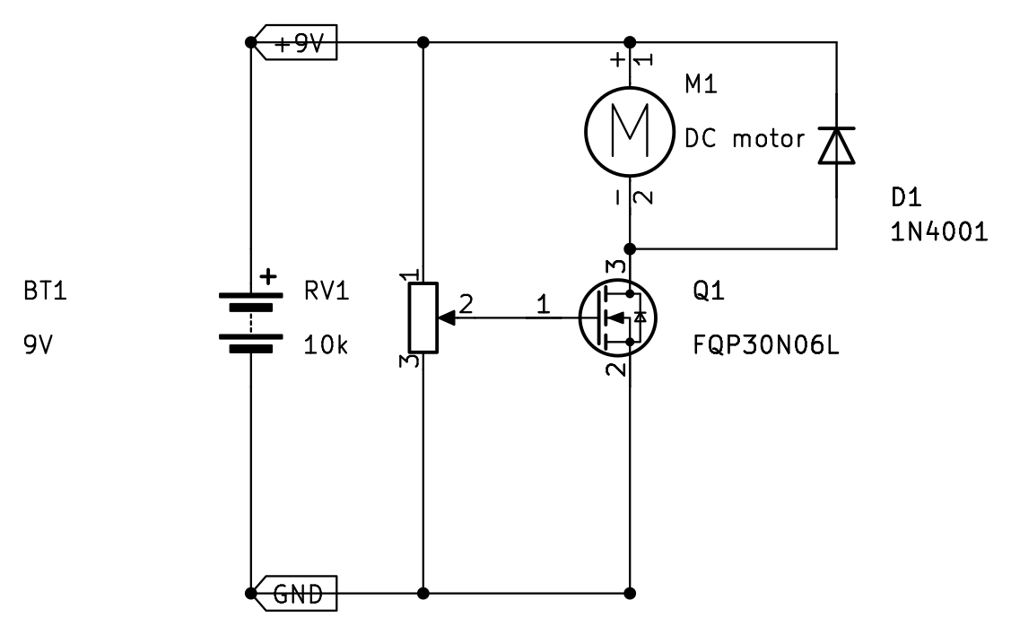

Prove it. Turn the trimmer across its range. Below the gate threshold the motor is dead; above it the motor spins, faster as the gate voltage rises. Measure the gate voltage with your multimeter as you turn the knob and watch the motor follow. A datasheet-grounded simulation of this part confirms that with the gate at 5 volts the MOSFET already passes full load current.5
Build 2: regulate and boost a battery
Build 1 switched a battery; this build conditions one, because raw battery voltage is never the steady rail a circuit needs. There are two moves, and you build both. To regulate is to hold a higher, sagging voltage steady at a lower value. To boost is to step a voltage that is too low up to the one you need.
First, regulate 9 volts down to 5. The 7805 is a three-pin linear regulator: voltage in, ground, a steady 5 volts out. Monk's rule is the one to remember: "any input voltage between 7V and 25V can be regulated to a constant 5V," and the two capacitors "provide little reservoirs of charge that keep the regulator IC operating in a stable manner."1 The 7 volt floor is the catch: the input must sit about 2 volts above the output, so a single 3.7 volt cell can never feed a 7805. Monk includes the capacitors because they "become much more necessary when the load varies,"1 and a Pi is a varying load.
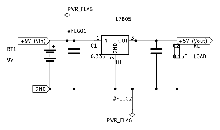

Regulating this way wastes the difference as heat. Monk warns that the 78 series is fine "for low-power circuits of a few hundred mA; however, above that, they start to get hot and may need a heatsink."1 A datasheet-grounded simulation confirms the behavior: 5.0 volts out while the input is 9, 7, or just above 7 volts, then regulation collapses once the input falls to the 7 volt floor.5
Then boost 3.7 volts up to 5. To run a Pi from one small lithium cell you need the opposite move. Monk describes it: a boost converter uses "an IC and a small inductor (coil of wire) and, by applying pulses to the inductor, produce a higher voltage."1 He points readers to inexpensive adjustable modules ("search for 'Boost Step-Up 3.7V'") and notes a combined board that charges the LiPo over USB while boosting its output.1 We build that combination from parts on hand: a 3.7 volt LiPo, a TP4056 charger, and an SX1308 boost module set to 5 volts. It does the same job as a commercial PiSugar supply, from parts you understand. One rating matters here: a mini slide switch in this class is a 0.5 amp part, and it sits on the cell line, where a hard-working Pi Zero 2 W can pull more than that from a 3.7 volt cell. The switch is fine for light loads like a microcontroller and a servo; for a hard-working Pi, size it up.

Prove it, and read the runtime. Set the module's trimmer until the output reads 5.0 volts, then load it with the Pi. Runtime follows the capacity rule from Unit 1, with one correction. Because a boost steps voltage up, it draws more current from the falling cell than the Pi draws at 5 volts, so a 450 mAh cell yields on the order of an hour under a light load and less under a heavy one, not the larger figure a naive capacity-over-load guess would give.1
Build 3: relay from a Pi
In this build the Pi throws a switch of its own. The board is a Pi Zero 2 W, the pocket-sized sibling of the Pi 5 that runs your Module 01 node, and its 40-pin header is the same. A relay, in Monk's words, "is basically an electromagnet that closes switch contacts," and "the fact that the coil and the contacts are electrically isolated from one another makes relays great for things like switching home-powered devices on and off."1 Where the MOSFET in Build 1 switched a load sharing its ground, a relay gives full isolation: the switched circuit shares nothing with the Pi.
A Pi cannot drive a relay coil directly. A GPIO pin is designed to source only about 16 mA,4 while the SRD-05VDC-SL-C's 70 Ω coil pulls about 72 mA at 5 volts,5 several times what the pin can safely give. So a small transistor does the driving, as in the relay driver Monk hand-builds in his Arduino chapter: a 2N3904 transistor, a 1 kΩ base resistor, a 1N4001 diode, and a 5 volt relay.1 You met the transistor and the diode as symbols and packages in Module 02, and the 1N4001 is the same diode you placed across Build 1's motor. On the module used here, a 1-channel relay board (high/low level trigger) carrying a SONGLE SRD-05VDC-SL-C relay, those parts are already on the board.
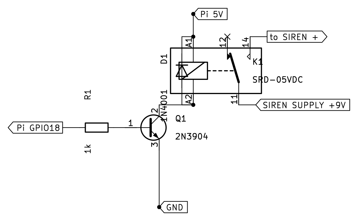

Prove it. Drive GPIO18 high and low. Monk's test is the sound: "if all is well, you will hear the relay module clicking on and off."1 The indicator LED lights, the isolated siren follows, and a multimeter confirms the siren circuit shares no voltage with the Pi.
Build 4: motion sensor and a Pi
The last build lets the Pi read a sensor. A PIR (passive infrared) sensor detects the moving heat of a person. Monk describes the module's behavior: "you just supply it with power and its output goes high (to supply voltage) when movement is detected and then back low again after a second or two."1
In this build you wire an HC-SR501 PIR module to a Pi Zero 2 W with three wires. Monk's mapping is ground to ground, VCC to 5 volts, and OUT to GPIO18.1

Prove it. Power the Pi, put your multimeter on the OUT line (DC volts, the same measurement you practiced in Module 02), and walk in front of the sensor. The line snaps from 0 volts to about 3.3, holds for the delay you set, then drops.
Field exercise
Combine three of your builds into one system: motion in, siren out. The PIR from Build 4 feeds the Pi, the Pi drives the relay from Build 3, and the relay sounds the isolated siren. The last task cuts the whole system over to the portable pack from Build 2, so it runs from one lithium cell.
Task: Build a motion-triggered switch: the PIR feeds the Pi, the Pi drives the relay, and the relay sounds an isolated siren.
Condition: Given your four proven builds, a Pi Zero 2 W, a breadboard and jumper wires, the siren with its own 9 volt supply, and a multimeter.
Standard: Motion in front of the sensor closes the relay and sounds the siren; the siren releases after the set delay; every connection matches your KiCad drawings; and the keeper is soldered to perfboard, not left on the breadboard.
Download the field exercise worksheet (PDF)
Next skill
You can now take a circuit from a drawing to a soldered, powered board, and switch, regulate, boost, and sense along the way. Module 04 turns to salvage: the parts, batteries, and boards you need are already around you, inside dead electronics, if you can identify them and desolder them cleanly.
Glossary
- boost converter
- A part that steps a voltage up, so a 3.7 volt cell can supply 5 volts. The SX1308 module here.
- capacity (mAh)
- How much charge a battery holds; capacity divided by the current drawn gives the runtime.
- cold joint
- A dull, rough solder joint made without enough heat; looks connected but is unreliable; the top beginner fault.
- flyback diode
- A diode across an inductive load, such as a relay coil, that absorbs the voltage spike when the current is switched off.
- logic-level MOSFET
- A MOSFET with a low enough gate threshold to be driven directly by a microcontroller pin.
- MOSFET
- A transistor switched fully on or off by a voltage on its gate; used to switch a heavy load from a light signal.
- perfboard
- A grid of soldered holes for making a breadboarded circuit permanent.
- PIR sensor
- A passive infrared sensor; its output goes high when it detects the moving heat of a person.
- regulator
- A part that holds its output at a fixed voltage below its input (step down). The 7805 gives a steady 5 volts and needs about 2 volts of headroom.
- relay
- An electrically operated mechanical switch; its coil, energized, closes contacts that switch a separate, isolated circuit.
- voltage sag
- The drop in a battery's voltage under load and as it discharges; the reason raw battery voltage needs conditioning.
Sources
- Simon Monk, Hacking Electronics, 2nd ed., McGraw-Hill, 2017. Primary source for the builds. MOSFETs as voltage-controlled switches and the logic-level FQP30N06L (Ch. 3, pp. 45–48); batteries, capacity, discharge rate, series and parallel, and LiPo safety (Ch. 5, pp. 79–93); the 7805 regulator and its 7–25 V input range and capacitors (pp. 93–95); boost converters (pp. 95–96); driving a relay from a transistor and the coil diode (Ch. 6, pp. 113–116); wiring a relay module to a Raspberry Pi (Ch. 7, p. 157); and the PIR sensor with a Pi and its 3.3 V output (Ch. 8, pp. 162–166).
- SRA, How to Solder Electronics: 15 Rules for Successful Soldering. The definition of solder and flux and the wetting process; the caution against running the tip at its maximum, where it oxidizes fastest; desoldering and salvage (get the joint molten fast, clear one joint at a time, never yank a part, and drain the capacitors first); and the fact that soldering smoke is burned flux, not lead vapor.
- Adafruit, Guide to Excellent Soldering. Making a good joint: heat both the pad and the lead, feed solder to the joint, and let it flow; the cold-joint failure mode and its repair by reheating.
- Raspberry Pi GPIO documentation. The 40-pin header used here (pin 2 = 5 V, pin 6 = ground, pin 12 = GPIO18) and the 3.3 V logic level of the GPIO pins.
- Manufacturer datasheets: FQP30N06L, L7805, SRD-05VDC-SL-C, 1N4001, SX1308, TP4056, HC-SR501. Part ratings, pinouts, and the values used to validate each build in simulation (the MOSFET at a 5 V gate, the 7805 output and dropout, and the relay coil spike with and without the diode).
- “Hacking When It Counts: POW Canteen Radios,” Hackaday, 2016. Lt. Col. R.G. Wells and fellow prisoners in a Japanese camp in Borneo (1942) built a radio receiver from improvised parts: resistors from string impregnated with burnt cinnamon bark, capacitors from tea-chest foil, wire insulation from flour and palm oil, and a chromic-acid wet cell from potassium dichromate and zinc trouser buttons; only the vacuum tube and headset could not be improvised, and the headset was smuggled in.
- “Foxhole radio,” Wikipedia. Improvised WWII receivers built from a razor-blade-and-pencil-lead detector; corroborates R.G. Wells building a receiver as a prisoner of war in Borneo in 1942.
- Jonathan Bartlett, Electronics for Beginners, Apress, 2020. The schematic as an abstraction where only the connections matter; the solderless breadboard's five-hole terminal strips, the centre gap that straddles a chip, and the power rails; and translating a schematic to a breadboard layout (Ch. 5-6).
- Alan Winstanley, The Basic Soldering Guide Handbook, 2014. Flux and wetting; leaded versus lead-free solder and melting points; the look of a good joint; heating the whole joint before feeding solder; desoldering-braid technique; burn first aid; and the coin-cell heating hazard.
- KiCad Eeschema documentation: the Electrical Rules Check. KiCad's ERC performs “automatic detection of incorrect and missing connections,” including unconnected pins and an input power pin “not driven by any Output Power pins.”
- Communications-Electronics Fundamentals: Solid State Devices and Amplifiers (TC 9-62), US Army. The schematic symbol of a diode and how it maps to the physical device (cathode bar, anode arrow), and reference designators such as CR1.
- Basic Electronic Components (ECK-10 Instruction Booklet), Elenco. Resistor and capacitor definitions and identification (colour bands, printed markings), solder composition and rosin flux, and the printed-circuit “Top Legend” that maps parts to the schematic.
- Voron FPV soldering guides (the Soldering Checklist and the Fundamentals of Soldering and Electrical Assembly), used with permission. The wire-to-pad technique (tin the pad, tin the wire, join them) and soldering temperatures for heavy versus small contacts; desoldering and salvage, including the caution that pressing braid down loosens and lifts the pad.
- Oscar Liang, Soldering Guide for Beginners (FPV). Iron temperature by the job: about 450 °C for heavy power contacts and roughly 390 °C for signal wires, with a larger tip for the heavy work; heat both the pad and the pin, then bring the solder to the joint; a long dwell can detach the copper pad.
- Hakko, soldering-iron temperature guidance. A tip temperature near 350 °C for leaded 60/40 or 63/37, and about 30 to 40 °C hotter (roughly 390–400 °C) for lead-free SAC305; tip temperature is set by the joint's thermal mass and the alloy, not a fixed number.
- Electrical Science, Module 4: Batteries (DOE-HDBK-1011/2-92), US Department of Energy. Cell fundamentals: electrodes and electrolyte; wet and dry cells; primary versus secondary cells; series and parallel wiring (four 1.5 V cells give 6 V in series, and parallel adds current capacity); ampere-hour capacity; and internal resistance dropping the terminal voltage under load (VL = VB − ILRi).
- David Linden and Thomas B. Reddy, Handbook of Batteries, 3rd ed., McGraw-Hill, 2002. Authoritative comparison figures (Tables 1.2, 7.3, 22.3): nominal cell voltage, specific energy, self-discharge rate, and cycle life for alkaline (1.5 V), lead-acid (2.0 V), NiMH (1.2 V), and lithium-ion and lithium-polymer (3.6 V nominal, 4.2 V full); and the practical capacity being only 20–30 percent of theoretical under real load.
- Micah Toll, DIY Lithium Batteries: How to Build Your Own Battery Packs. The lithium-ion and LiPo voltage window and the correction that most “LiPo” cells are lithium-ion pouch cells; the C-rate; series (S-count) and parallel pack math and the rule to match cell voltages before joining them in parallel; voltage sag; constant-current, constant-voltage charging; thermal-runaway thresholds; and using salvaged cells conservatively.
- “How to Salvage and Repackage Old 18650 Li-ion Cells,” Instructables. Sourcing 18650 cells from dead laptops, power banks, and tools; opening a pack without shorting or puncturing a cell; inspecting and discarding dented cells; capacity-testing and labelling each cell; the shelf-drop leakage test; and the roughly 3.6-volt half-charge storage level.