On this page
Power and the irregular force
The obvious way to power equipment away from the mains is a gasoline generator, and a generator produces noise, heat, and exhaust that carry to anyone nearby and that an adversary's sensors detect from beyond earshot.76 This module powers equipment without one.
There are two ways to do it quietly. The first is to draw from a building's existing electrical service. You read the panel, find a branch circuit with headroom, and put your load inside the building's normal draw.3542 That path carries a relay node pulling under a watt,64 and it ends at the circuit's rating. The second is a battery bank, a set of batteries wired together as one supply, charged from the wall or from a solar panel. A bank works where no service exists, and it is the path the quietest sites take.
Every build in this module is graded against one standard: Capable and Quiet. Capable means the supply is sized to a load you measured with your own meter, with a runtime you computed and then proved on the bench. Quiet means no generator hum, no heat or light tell, and a build you can conceal. Volume I states the design goal for a remote comms site: via solar power and auxiliary batteries, the system will remain on the air in the event of failure of the electrical grid.1
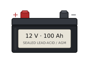
Every sizing decision comes down to one measure: the watt-hour (Wh), the amount of energy a battery holds or a load consumes. Module 02 gave you watts, volts times amps. Module 03 gave you battery capacity in amp-hours. Multiply a battery's voltage by its amp-hours and you have its stored energy: a 12-volt battery rated at 100 amp-hours holds 12 × 100 = 1,200 Wh.80 Multiply a load's watts by its hours and you have its demand: a 10-watt light running 5 hours consumes 10 × 5 = 50 Wh.81 Both sides land in watt-hours, so you can compare any battery against any load, whatever the voltage or chemistry.
Read the grid from open sources
Before you walk to a structure, read its electrical service from a screen. Open sources give you which utility feeds the building, what voltage reaches it, whether the line is live, and where the nearest substation sits.
The utility feeds the structure through a transformer, past the meter, to the main panel; the panel then divides that supply into the branch circuits that serve the building and, sometimes, into subpanels deeper inside.
Start in OpenStreetMap, a free public map anyone can query. OpenStreetMap records the electrical grid under the power key, which covers the facilities that generate and distribute electrical power.58 The tags to look for are power=line, minor_line, tower, pole, transformer, and substation.58 You used Overpass Turbo (overpass-turbo.eu) in Module 04 to query OpenStreetMap for salvage sites; the same tool queries the grid. Paste the following query, move the map over the target, and press Run.
[out:json][timeout:60];
(
  nwr["power"="transformer"]({{bbox}});
  nwr["power"="pole"]({{bbox}});
  nwr["power"="tower"]({{bbox}});
  nwr["power"="line"]({{bbox}});
  nwr["power"="minor_line"]({{bbox}});
  nwr["power"="substation"]({{bbox}});
);
out center;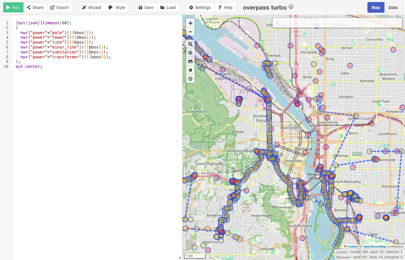
The result plots poles, lines, transformers, and any mapped substation, so you can read which direction the feed comes from and whether the service is overhead distribution or a nearby underground lateral. Open Infrastructure Map renders that same OpenStreetMap data as a finished grid map.59 You can trace a substation along its distribution lines to the target without writing a query.
OpenStreetMap tags a substation power=substation: the facility where transformers, switchgear, or compensators control the flow of electricity through the network.65 Its voltage tag lists the substation's voltages from highest to lowest.65 Read it in that order: the first number is the voltage coming in, the last the voltage going out. A live query over inner Portland returns Holladay Substation, operated by PacifiCorp, tagged substation=distribution with voltage=115000;12470: 115 kV in, 12.47 kV out. That drop from transmission voltage to distribution voltage is what you read at the pole transformer in Unit 03; record both voltages before you go to the site. A substation tagged substation=transmission carrying a longer voltage list sits further up the chain and does not feed structures directly.
Querying by radius instead of map view narrows the result from a city-wide set to one structure's surroundings. You pass the Overpass around filter a radius in meters, a latitude, and a longitude, and it returns only the features within that distance of the point.66 The nwr at the start of each line is shorthand for nodes, ways, or relations,66 so one line covers all three element types.
[out:json][timeout:90];
// everything electrical within 300 m of one point
(
  nwr["power"="pole"](around:300,45.5152,-122.6784);
  nwr["power"="minor_line"](around:300,45.5152,-122.6784);
  nwr["power"="transformer"](around:300,45.5152,-122.6784);
  nwr["power"="substation"](around:300,45.5152,-122.6784);
  nwr["power"="generator"](around:300,45.5152,-122.6784);
  nwr["man_made"="street_cabinet"](around:300,45.5152,-122.6784);
);
out center;
OpenStreetMap maps a ground-level utility box as man_made=street_cabinet, the roadside cabinet that holds distribution gear for power or street lighting.67 Add utility=power to narrow it to a cabinet holding electrical gear.67 On-site generation is mapped as power=generator,68 with generator:source=solar naming the source. A structure with tagged generation has a second supply feeding its panel; Unit 04 shows you how to read that second supply at the breaker.
Utilities publish live outage maps that let you check whether a grid segment is energized without approaching the site. Florida Power and Light runs an online interactive map that shows where power is out anywhere in its service territory.69 The limit is granularity, and the utilities state it themselves. FPL withholds address-level detail and says so: for safety and security reasons, its Power Tracker does not display outage information for specific street addresses.69 Orange and Rockland places each outage symbol at a center point among all the customers that outage affects. One symbol can therefore stand for several homes and businesses, covering several streets, or miles in a major event, and the map updates every 15 to 30 minutes.70
For the transmission end, the Homeland Infrastructure Foundation-Level Data program publishes public geospatial datasets of electric power transmission lines through data.gov.71 Confirm a portal is still live before relying on it. The U.S. Department of Homeland Security shut down HIFLD Open, its public data portal, in August 2025, and the open datasets were preserved in the Homeland Security Digital Library instead.72
Many jurisdictions publish assessor and electrical-permit records, which give the year built and sometimes the service size and inspection history. They are the paper trail behind the panel's “APPROVAL FOR ELECTRICAL” sticker. Availability varies by jurisdiction, so do not count on them. Sanborn fire-insurance maps, public-domain and held by the Library of Congress,60 give a building's footprint and construction. They were drawn for fire underwriting, and many editions predate electrification, so they do not reliably show electrical service. No open database holds the structure's internal wiring, its branch-circuit layout; you read that on site, at the panel.
Open-source reconnaissance cannot give you the state of the service: for that you go and look, still without touching anything.
Read the service from outside
Power reaches a building one of two ways: overhead from a pole, or underground from a pad. Which path feeds the structure tells you where the transformer, the meter, and the main disconnect sit. You read the transformer and the meter from outside the building. The main disconnect is inside the wall.
The service is the conductors and equipment for delivering energy from the utility to the building's wiring.50 An overhead supply drops from a pole transformer. Those overhead conductors from the last pole to the building are the service drop.54 They hang in a drip loop, a downward arc of slack that lets rainwater fall off before it can follow the conductors in. The conductors enter through the masthead, a weatherproof fitting at the top of the service mast.44 The mast is the conduit that carries them down the outside wall. A buried supply runs underground as a service lateral, from the street main to the first point of connection at the building.54 Either path ends at the meter and passes into the panel.
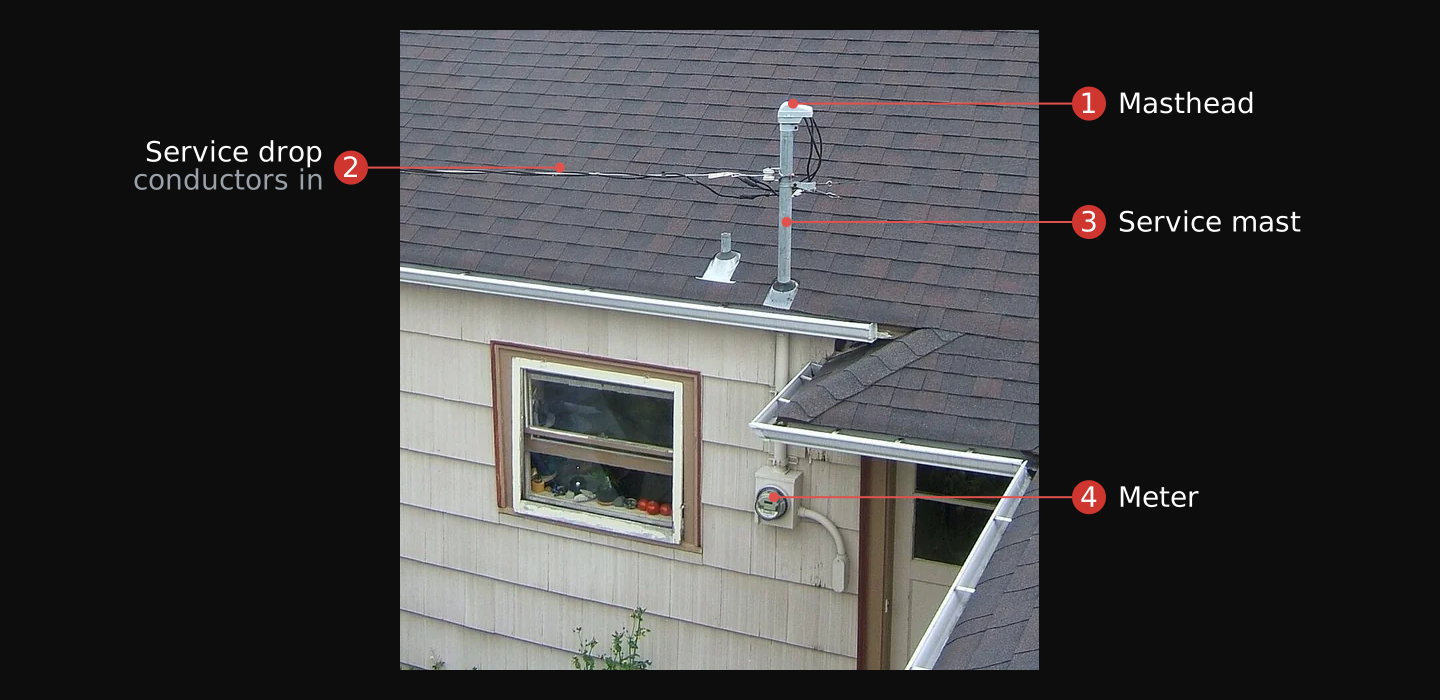
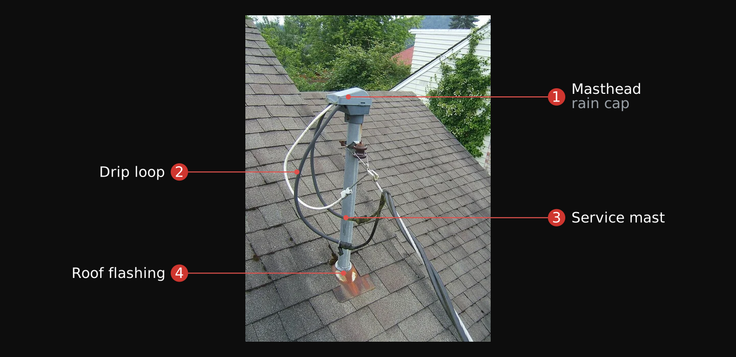


The service point divides the two sides. It is the point of connection between the facilities of the serving utility and the premises wiring.54 Everything upstream of it (the pole hardware or the pad) belongs to the utility and carries its voltages. The meter, the disconnect, and the wiring downstream are the premises side you read.
On a pole, the transformer hangs below the primary conductors, which carry distribution voltage, typically 12 to 34.5 kV.55 Between the primary and the transformer sit a fuse cutout and a surge arrester, both visible from the ground at a riser pole where an overhead line meets an underground run.55 The service drop runs from this transformer to the building.
Underground, the transformer is a pad-mounted box at ground level. The buried lateral reaches the structure through handholes or pull boxes, running from the street main to the first point of connection at the building.54
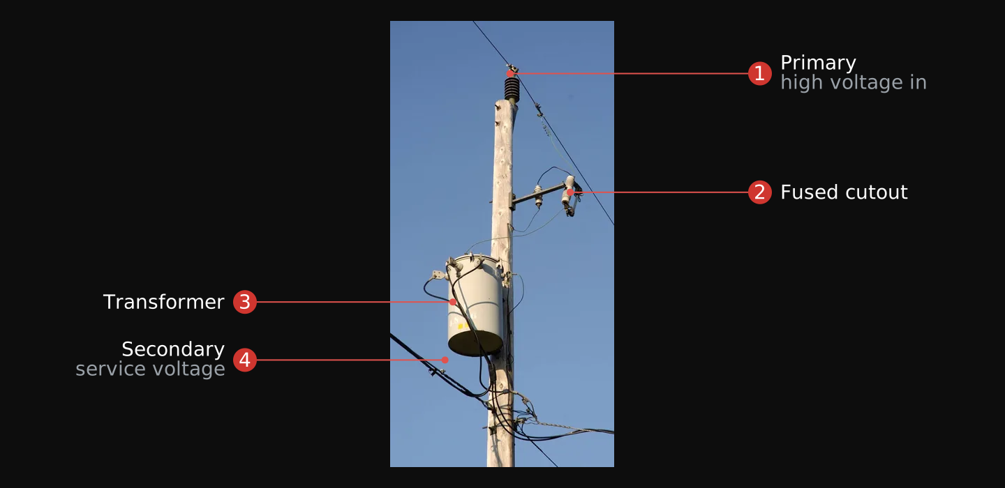
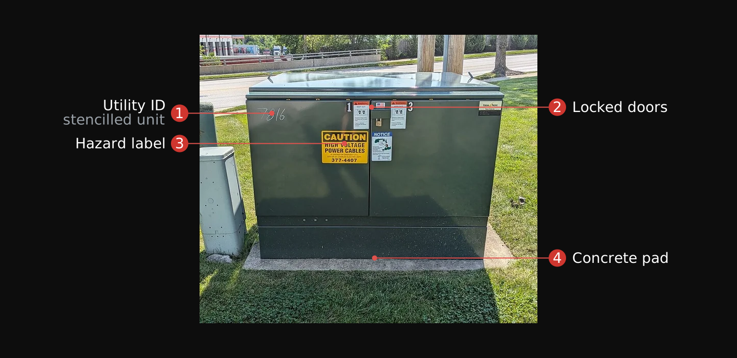


All lines are considered energized until they are completely disconnected and isolated from all electrical power sources.51 The primary side, at distribution voltage, is beyond any lay operator: TM 5-682 restricts work on energized equipment at 17,000 volts and above to qualified personnel.51 Identify the pole or pad to tell overhead from underground and to locate the service point. Read the secondary side from there, and stay clear of the primary.
You read whether a structure is drawing power before opening anything. A fire-service procedure for evaluating vacant buildings puts the power check early in the exterior survey: observe the status of the utility meters and valves on the outside of the building to determine whether electricity and water are available.56 Of those exterior indicators, the meter gives the clearest reading of whether a structure has power.
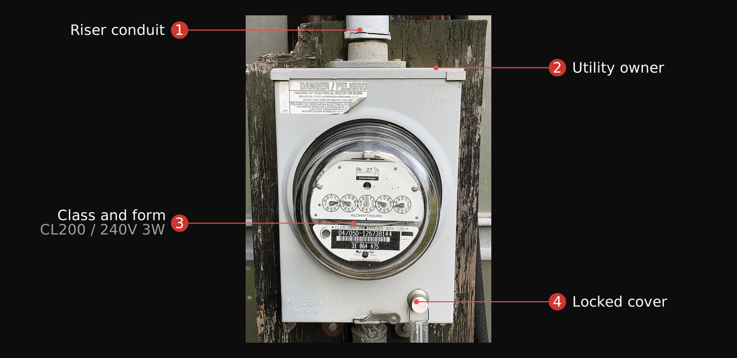
An older electromechanical meter carries an aluminum disc that turns at a speed proportional to the power passing through it.57 Each revolution passes a fixed amount of energy, the meter constant Kh, in watt-hours per revolution.57 A turning disc means current is flowing; a still disc means little or none. The Kh constant is printed on the nameplate: 3.6 watt-hours per revolution on the Westinghouse below. Read the disc to determine whether the building is drawing power or sitting idle. Take current measurements at the panel with the clamp meter, covered in Unit 04.
A newer smart meter replaces the disc and dials with a digital register showing a cumulative total of energy delivered,73 and records consumption in intervals as fine as 15 minutes.47 Neither type of meter shows present demand as a number, so a turning disc on an electromechanical meter is the only live reading visible through the glass.
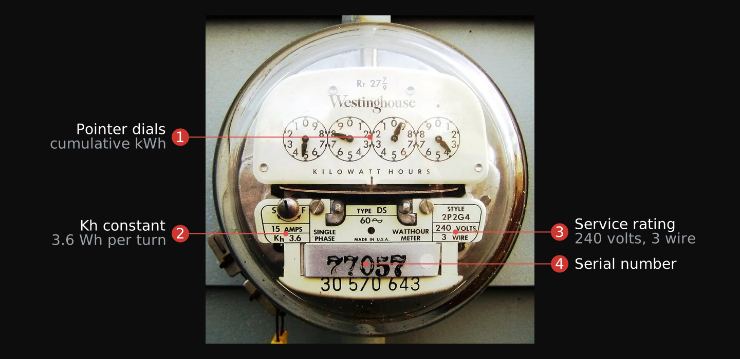
- Pointer dials. A running total of energy, read left to right. Not present demand.
- Kh constant. Watt-hours per turn of the disc. This meter, 3.6.
- Service rating. 240 volts, 3-wire: the split-phase supply (Unit 04) the panel divides.
- Serial number. Identifies this meter to the utility.

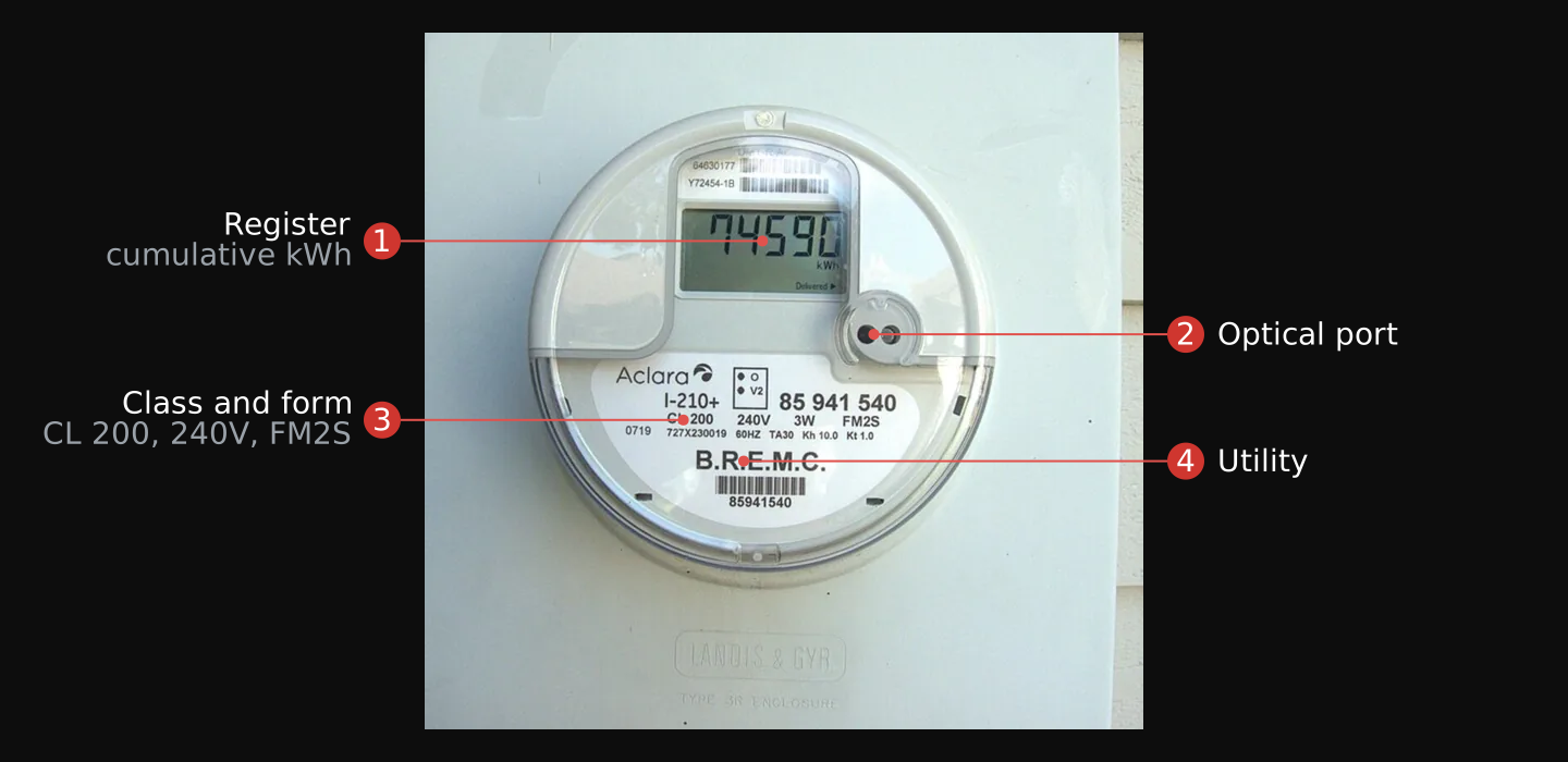
- Register. A running total of energy delivered, not what the building draws now.
- Optical port. The local read point. A smart meter also transmits its data over the air to the utility's collection network.
- Class and form. The meter's own current rating and socket form, not the service size. The service rating is set by the main disconnect, read in Unit 04.73
- Utility. Names the operator, which you look up to find the tariff, the outage map, and the service territory.

A drop still running from the transformer to the masthead, or a lateral connected from the pad to the structure, means the utility feed is in place. At the wall, the meter sits in a socket enclosure. The socket is the fixed half mounted on the wall, and the meter is the removable half that plugs into it. An empty socket means the meter is gone, not that the service is dead. Utility practice on disconnection varies, so an empty socket, a dark display, or a still disc is a reason to confirm, not proof. Treat the service as energized until it is proven disconnected and isolated.51
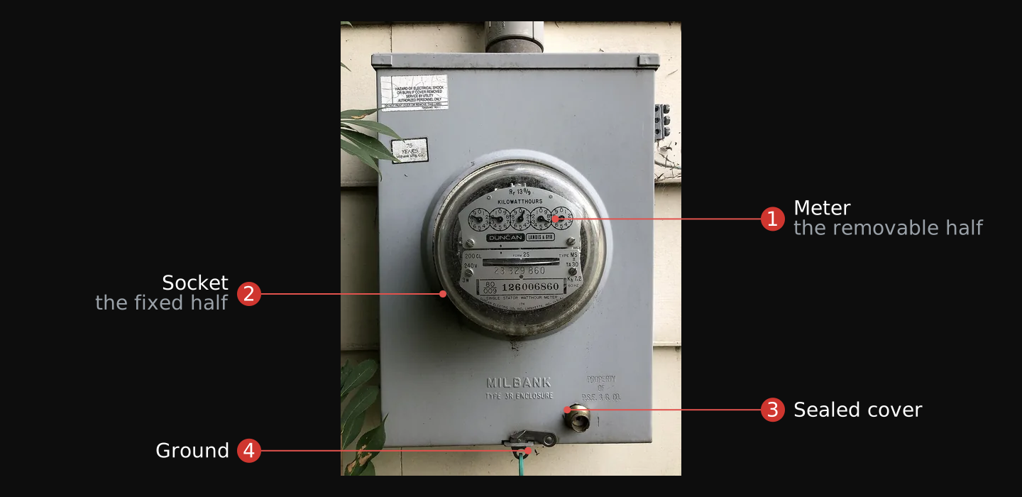

_in_the_Mountainview_section_of_Ewing_Township,_Mercer_County,_New_Jersey.jpg)
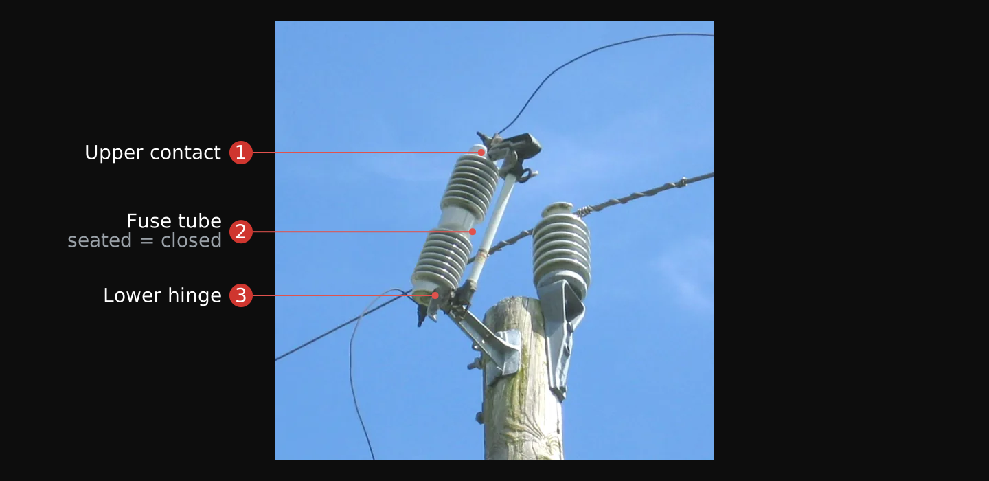
From the street you can also read the fuse cutout on the pole. A cutout is a protective device on the primary side, rated to protect the transformer or the feeder that supplies it.55 It carries its fuse in a hinged holder that bridges two contacts. A seated holder means the cutout is closed and in service. A blown fuse drops the holder open so it hangs down, visible from the ground.82 Because the cutout sits in series with what it protects, an open holder means the protected circuit is interrupted at the pole.

Read the panel
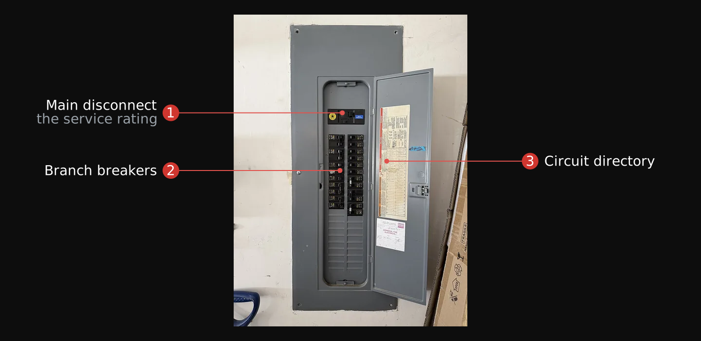
At the panel you open the door and read the main disconnect's rating, each breaker's rating, and the circuit directory. The cover over the live bus bars, the dead front, stays on the whole time you do this. You measure what a circuit actually carries separately, with a clamp meter at a reachable point downstream of the breaker. Together, those two reads decide whether the structure has a circuit you can draw from without tripping a breaker or stepping up the meter's recorded profile.

Before you start, have the multimeter from Module 02, a clamp meter, a line splitter, and a non-contact voltage tester on hand. The clamp meter and voltage tester are new to this module; the line splitter is a plug-in adapter that costs a few dollars. The parts list below describes each one.
The main disconnect, the single breaker or switch that cuts all power to the panel, sets the size of the service. Its amperage is stamped on the breaker or printed on the panel label, and that number is the ceiling on everything the building draws at once; read it first.36 Residential services commonly run 100 to 200 amperes.44 A one-family dwelling must carry at least a 100-ampere, 3-wire disconnect; other installations floor at 60 amperes, and one- or two-circuit services at 15 or 30.34 When the main is not labeled, read the size from the service-entrance conductor, since a larger service needs a larger conductor:44 a 200-ampere service runs 2/0 copper (or 4/0 aluminum), a 100-ampere feed 3 AWG copper.44
Most homes take a 120/240-volt service, where the cable assembly carries two ungrounded (live or hot) conductors, each supplying 120 volts, and one neutral or grounded conductor that acts as the return.44 Either hot leg to the neutral is about 120 volts and runs the lights and outlets; the two hot legs across each other are about 240 volts and run the range, the dryer, and the other large loads. The transformer makes both by tapping the center of its secondary winding: the center tap is the grounded neutral, each half of the winding is one 120-volt leg, and the two legs across the whole winding are 240 volts. The amperage rating is how much the two legs carry together.

From the main disconnect the panel divides the service into branch circuits, each protected by its own breaker, and the breaker rating is the circuit rating. A branch circuit takes the rating of its overcurrent device, and the code sets those ratings at 15, 20, 30, 40 and 50 amperes.35 A 15- or 20-ampere breaker commonly feeds general lighting and receptacles; 30, 40, and 50 feed larger fixed loads. The breaker opens the circuit on overcurrent, the condition in which a circuit carries more than its rated load in amperes; fuses, circuit breakers and GFCIs are the devices that prevent it.37 That rating sets the circuit's ceiling, and the spare capacity left below what it already carries is the circuit's headroom. The code sizes a circuit with a margin for steady loads: the overcurrent device rating “shall not be less than the noncontinuous load plus 125 percent of the continuous load.”42 A continuous load should stay at or below 80 percent of the breaker rating, so a 20-ampere circuit holds about 16 amperes of steady draw.


A ground-fault circuit interrupter (GFCI) disconnects the circuit when the current in the energized conductor and the current returning on the neutral do not match. That mismatch is the leak that would otherwise flow through a person. The code requires one on outlets in bathrooms, outdoors, unfinished basements, kitchens, and other wet or grounded locations.43 An arc-fault circuit interrupter (AFCI) de-energizes the circuit when it detects an arc fault,43 protecting the wiring against arcing. Both are still breakers, and you read them the same way. Some slots hold two thin tandem breakers instead of one, so count the circuits, not the slots.
A subpanel, also called a distribution panel, is a second panel fed from the main; it carries no disconnect of its own, because the main disconnect upstream already covers it.44 It sits elsewhere in the structure: a garage, a basement, an addition. When the directory marks a feed for one, find the subpanel and read it too. A structure's power is the main panel plus every subpanel it feeds.
Some structures are not powered from the grid alone: on-site generation (solar, a battery, or a generator) feeds the panel through an inverter, a transfer switch, or a backfed breaker. Where a second source is present, the code requires a permanent plaque at the service equipment naming every power source on the premises,49 so the panel itself should tell you what else feeds it. A generator ties in only through transfer equipment built to keep the two supplies from ever connecting at once,26 and that equipment usually controls a subpanel feeding a few critical circuits: lights, outlets, and essential appliances.48 Whatever ties in this way stays live when the grid goes down. The common case is a single-family, grid-fed, 120/240-volt service; commercial and multi-unit buildings take heavier services, often three-phase, read with more legs and more panels.
To follow a circuit from the panel to where you would use it, read the wiring method. Conduit comes in a few identifiable types: rigid steel, thin-wall steel tubing (EMT), PVC, and flexible metal.38 The type and its route tell you where a circuit runs and where you can reach it.

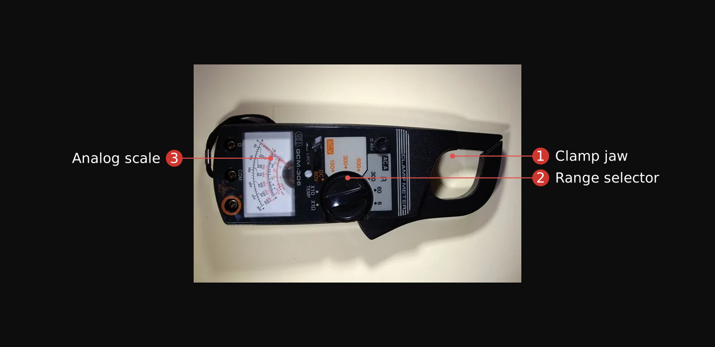
To size a real draw you measure the current a circuit carries, not the breaker number, with a clamp meter. A clamp meter combines a digital multimeter with a current sensor: pressing the trigger opens the jaw, and you close it around one wire of the circuit without touching that wire, so the measurement is non-contact.39 The jaw is a current transformer: the hinged ferrite-iron jaws close into a ring that concentrates the magnetic field around the conductor, a coil wound on that core is the secondary winding, the conductor inside the jaw is the single-turn primary, and the induced current is scaled down and shown as amps.39 Clamp one conductor only, never a whole cord, or the line and neutral currents cancel out.

At a receptacle, you cannot separate the conductors inside a cord by hand, and a jaw closed around the whole cord reads nothing, because the two conductors' magnetic fields cancel.83 A line splitter does the separation for you. Plug the splitter into the receptacle, plug the device's cord into the splitter, and the splitter routes one conductor through a loop the clamp jaw fits around. Set the clamp meter to amps AC, close the jaw around that loop, and read the current while the device runs.83 The number on the display is the draw through that device. Turn the device off and the reading drops to zero; the splitter carries only the one device plugged through it.
A tap point is an accessible connection to a branch circuit that has headroom. Which points you can use depends on your access:
- From outsideYou can reach GFCI-protected receptacles, which the code requires outdoors,43 the meter base on the exterior wall, and any disconnect mounted outside.
- From insideYou can reach every receptacle, switch box, junction box, and subpanel44 on a branch circuit, including interior circuits that are out of reach from outside, such as a bedroom's receptacles or a closet subpanel.
What is hardwired with no receptacle, a furnace or a dedicated 240-volt appliance run, is not a tap from either side. A breaker with headroom and a reachable point make a usable tap only when both are on the same circuit; confirm that by switching the breaker off and noting which receptacles and fixtures lose power.
Everything downstream of the meter is the load side, and current drawn there passes through the meter and adds to its count. A tap ahead of the meter, on the supply side, draws current straight from the utility's own conductors; that current never reaches the meter, so nothing registers.
A tap can be detected three ways:
- Protective devicesA draw over the circuit's continuous limit trips the breaker;42 current that returns on a path other than the neutral trips a GFCI.45
- The meterSmart (AMI) meters record kilowatt-hour (kWh) consumption in intervals as short as 15 minutes,47 so a load-side tap shows as a step in the recorded profile. Keep the draw small against the structure's load profile, the ordinary rise and fall of its power use through the day; a supply-side tap shows nothing at the meter.
- The supplyA switch-mode supply pushes radio-frequency noise back onto the wiring; the FCC limits the radio-frequency voltage a device conducts back onto the AC power line across the band 150 kHz to 30 MHz.46 That conducted noise is a signature on the line: a supply held to the limit stays under it, a failing or uncertified one does not.

Put the reads together into one pass over a structure:
- Find the meter. Outside, note whether the service comes in overhead (down a mast to the masthead) or underground.
- Read the main disconnect. At the panel, with the dead front on, read its amperage. When it is not labeled, infer the size from the service-entrance conductor gauge.
- Read the directory. Note which breakers feed what, and each breaker's rating.
- Find the subpanels. Follow any feed marked for a distribution panel and read that panel the same way.
- Measure a draw. With a clamp meter set to amps AC and a line splitter, clamp one conductor of a running load and read the amps it carries.39 The reading rises when the load turns on and falls when it turns off.
- Compute the headroom. Take 80 percent of the breaker's rating as the continuous limit, then subtract the measured draw.
- Locate the tap points. Given your access, list the reachable points that sit on circuits with headroom. From outside those are exterior receptacles and any outside disconnect. From inside they are receptacles, junction boxes, and subpanels. Confirm a point and a breaker are the same circuit before you count it.
- Check it blends in. Keep the tap under the 80 percent limit and on one hot-and-neutral pair, so no breaker or GFCI trips. Keep the steady draw small against the structure's load profile, so it does not step up an interval-recording meter. Use a clean supply, so it adds no powerline noise.
- ReadThe main disconnect is rated 200 A, the circuit's breaker 20 A, and the clamp meter reads 6 A with the load running.
- Circuit limit20 A × 0.8 = 16 A continuous.
- Circuit headroom16 A − 6 A = 10 A left on this circuit.
- ServiceThe two legs together stay well under 200 A, so the service ceiling is not the limit here.
- ResultA steady draw of a few amps fits under the 10 A circuit headroom and the 200 A ceiling. It neither trips the breaker nor stands out.
Tap the supply
A tap that trips a breaker, steps up a meter, or leaves visible wiring announces the site. The connection itself must be as quiet as the power source it feeds.
With a point chosen and its headroom known, you make the tap: match it to the circuit, size and protect it for its draw, and isolate it from the utility. There are two ways in: plug into a receptacle, or splice into a box. The receptacle tap needs only a cord, an inline fuse, and the device. The junction-box tap adds a voltage tester, wire connectors, insulated hand tools, and rated wire; the parts list below names each one.
Make the tap in this order:
- De-energize it, or plug in. At a receptacle you plug in and open nothing. To wire into a box or a fixture, switch the circuit off at its breaker and confirm it reads no voltage with an approved tester; treat every line as energized until you have proven it dead.51
- Match conductor to conductor. Join hot to hot, neutral to neutral, and ground to ground with proper wire connectors and insulation matched to the conductors,52 and enclose the splice in a box.53
- Size your own conductor. Your tap's cord or wire carries the current, so size it to the load; conductors are “protected against overcurrent in accordance with their ampacities.”18
- Fuse the tap. Put an overcurrent device in series with your hot leg, rated to your conductor and load. A fuse becomes part of the circuit once it is installed in series with the hot wire, and its element sets how much current passes before it opens.37
- Never back-feed. Do not energize the premises wiring or the utility side from your own source. A generator connects only through transfer equipment built to keep the two supplies from ever connecting at once.26 OSHA's rule is categorical: never attach a source to a structure's electrical system without a properly installed transfer switch, because doing so creates a risk of electrocution for utility workers.84 Your bank powers its own loads on its own wiring; it never feeds a wall receptacle.
- Stay under the headroom. Hold the draw under the circuit's 80 percent limit and the service ceiling you read in Unit 04, so no breaker or GFCI trips and nothing steps up on the meter.
The taps above are the self-study skill: load-side, reachable, inside the building. The field exercise tests them. Read the rest of this unit for recognition and planning, not for practice; the in-person course covers supply-side and height work under direct supervision.
Reaching power from the outside is the harder case, and two things set its limits: which side of the meter you are on, and which voltage you are near.
Only the secondary side is approachable. The service drop, the service-entrance conductors, and the meter run at 120/240 volts, the same as the branch circuits inside. The primary side, which includes the pole lines, the transformer's high side, and the cutouts, runs at medium voltage, typically 12 to 34.5 kV for local distribution.55 It is lethal and utility-only, as Unit 03 established, and nothing on it is ever a tap.
A connection made ahead of the meter is a supply-side connection, and the code treats that location as a special case. It allows only a closed list of equipment on the supply side of the service disconnect: meters, current-limiting devices, instrument transformers, and specific standby and interconnection taps.61 None of those is a load. A load drawn there is outside what the code permits, and because it sits ahead of the meter it is unmetered: the current never passes through the meter's counting register. It is also more dangerous than a load-side tap, because no breaker sits between you and the transformer, so the conductors are live and their current is unlimited, and they stay energized until proven isolated.51
Reaching an exterior drop or service point can mean working at height and near live conductors. Above four feet on a pole or tower, OSHA requires a personal fall arrest system, work-positioning equipment, or fall restraint before any electrical work begins.62
The standard for electrical protective equipment covers rubber insulating gloves among other equipment,63 and rates each glove by class to a maximum use voltage:
| Glove class | Maximum use voltage, ac |
|---|---|
| Class 00 | 500 V |
| Class 0 | 1,000 V |
| Class 1 | 7,500 V |
| Class 2 | 17,000 V |
| Class 3 | 26,500 V |
| Class 4 | 36,000 V |
For 120/240-volt secondary work, Class 00 or Class 0 covers the voltage. The higher classes cover the medium-voltage primary, but a glove's class rating certifies only the voltage it withstands, not the competence to work an energized line. “Under-rated protective equipment should not be used,”51 and no glove makes the primary side approachable.
The Dolos platform is a small computer that reads sensors, transmits data, and controls outputs, and a sensor or comms node built on it draws very little. A Raspberry Pi Zero 2 W idles at about 100 mA (0.6 W) with its video and status LED off (third-party measured),64 a few thousandths of an amp at 120 volts. Against a branch circuit with several amperes of headroom, that draw fits under the 80 percent limit with room to spare and stays inside the structure's load profile, so an interval meter does not step up on it. Read the service in Unit 04, size the headroom, and make the tap under it; the structure's own power then runs the node. The Dolos is one platform that fits there, not the only one; size any load the same way, against the headroom you read.
Read the load
You size the bank to one number: what your equipment actually draws. That number does not come from a label, a manual, or a forum table. A label states the maximum the power supply was designed for, and the running draw of a medical device, a radio, or a terminal moves with what the device is doing. So the number comes from the multimeter on your Module 02 bench, on your own equipment, while it runs.
Set the meter to DC amps, put it inline on the load's positive lead, and read the current while the device does its real job. Multiply that current by the system voltage and you have watts: V × I = W. A device that reads 0.7 A on a 12-volt bank draws 12 × 0.7 = 8.4 W. Two kinds of loads need more than one reading. A radio draws a small current receiving and a much larger one transmitting, so read both and weight them by the duty cycle, the share of the hour spent in each mode. The battery handbook sizes radio batteries the same way, with a worked military-transceiver example: 50 milliamps on receive, 1 amp on transmit, at a 9-to-1 receive-to-transmit duty cycle.9 A device with a starting surge, a compressor or a suction unit, gets read at start and at steady state, and the bank must carry the surge.
- Read each load's running current with the meter inline, and multiply by the voltage for watts.3
- Turn watts into a daily budget. Multiply each load's watts by the hours a day it runs, then add the loads up.3
- Add a quarter for margin: budget times 1.25, a planning margin that covers conversion losses and the loads you add later. That number is what the bank must carry per day.
The daily budget varies by orders of magnitude across applications. A Dolos sensor node drawing 0.6 watts around the clock needs 0.6 × 24 = 14.4 Wh per day. A comms relay running a Starlink Mini at 30 watts for 8 hours a day needs 30 × 8 = 240 Wh. A clandestine trauma suite drawing 150 watts of suction, lighting, monitoring, and comms for 4 hours needs 150 × 4 = 600 Wh. The measurement is the same; the bank and the panel scale to the number.
Take one DC device you own and measure its running draw. An LED strip on a 12-volt supply, a DC fan with bare leads, or any circuit from your Module 03 bench works; if you have an HT radio, read its receive and transmit draws separately. Set the meter to DC amps, put it inline on the positive lead, run the device at its real job, and compute watts: the reading times the supply voltage.
Verify: a written figure in watts, from your own meter, dated. That number, not the label, is what every later sizing step uses.
The Starlink Standard dish is one load worth sizing against. Its own DC power supply takes 12 to 48 volts DC in at up to 30 amps, feeds the dish 56 volts DC, and is weather-rated to IP66.4 That input range means it runs off a 12-volt bank directly, with no inverter anywhere in the path. The Standard 4X specification sheet lists an average power consumption of 75 to 100 watts.74 The Starlink Mini draws less: an average of 25 to 40 watts from a 12 to 48 volt DC input, weighs 1.10 kg, and carries integrated WiFi with one ethernet LAN port.75 Either terminal is a battery-and-panel load that needs no inverter, and neither publishes real-time demand, so each gets the same treatment as every other load: the meter, inline, while it runs.
The interactive below runs the sizing arithmetic on your own numbers: the current you measured, the daily run time, and the battery you found. Run your measured loads through it before Unit 07 and write down the daily watt-hour figure, because every later unit sizes against it.
Interactive Power budget · size the battery and panel Enter the current you measured, the daily run time, and the battery you found; read back daily watt-hours, usable capacity at your chemistry's depth of discharge, days of storage, and the panel that replaces a day. Open it full screen →The battery you can source
This unit requires the salvage skill from Module 04. If you have not done Module 04's field exercise, do it now; every battery source below comes from the discard stream that exercise taught you to work.
The main battery of this module is the 12-volt lead-acid block, and it holds that role because it turns up everywhere. Volume III reached the same conclusion working the drone problem: power supply is one of the most significant limitations of sustained drone operation, and the regeneration methods it lists are larger batteries, like a car battery or LiFePO4, generators, and the apparent outlet.2 Every battery taught here exists in volume in the discard stream Module 04 taught you to work, not in a specialty channel, so nothing here depends on a find you cannot make. Three finds fill three roles, ranked by how easily you reach them:
- The UPS battery is the battery you learn on. Offices discard UPS units continuously, and a dead UPS is usually a good box with a worn battery, because the sealed battery inside has a service life of only three to five years.5 Module 04 taught the teardown that recovers it. The pull is small and often worn, which is why the test procedure below exists. A good one runs your bench. The UPS box itself is your first charger: plug it into mains power, reconnect the battery, and the box holds it on the constant-voltage float charge that standby service calls for.9 Even with a worn battery, the box gives you a charger and an enclosure.
- The car battery comes from a self-service junkyard for the fee at the gate, in cash,6 and it holds several times what the UPS pull holds. It is a starter build with thin plates for cranking, so it carries a site only if you keep the discharges shallow. The cycle-life figures below state what deep draws cost it.
- The deep-cycle block is the one to build the real bank on; it is worth the search. A discarded mobility scooter carries sealed 12-volt AGM blocks built to be recharged hundreds of times,7 and a commercial floor scrubber carries deep-cycle lead-acid blocks in the same voltages.8 Scooters and scrubbers reach the discard stream less often than UPS units, but they are trade equipment, not a niche product.
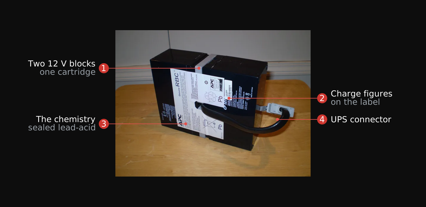
- The cartridge holds two 12 V blocks strapped as one unit; each comes out and tests separately.
- The charge figures on the label print the maker's own profile: cycle use 14.5 to 14.9 volts, standby 13.6 to 13.8. Unit 10 runs on these numbers.
- The chemistry is sealed, non-spillable lead-acid: the VRLA family, safe indoors in any orientation.
- The UPS connector is where the cartridge plugs in; cut nothing, it unplugs.

Learn on the free UPS pull, use the junkyard block when it is what you have, and build the real bank on the deep-cycle block or the LiFePO4 pack of Unit 08.
Inside the case, a lead-acid cell holds 2.0 volts nominal, so the 12-volt block is six cells in series, and a healthy block at rest reads about 12.3 to 12.75 volts open-circuit, 2.05 to 2.125 volts per cell depending on design.9 The sealed form you will find most often is VRLA (valve-regulated lead-acid), usually built as AGM (absorbent glass mat): a porous mat of microglass fibers holds the electrolyte instead of loose liquid, which lets the battery operate in different orientations without spilling.9 The cost of the chemistry is weight. Lead-acid stores about 30 to 40 Wh/kg,9 starters a little more and deep-cycles a little less,10 a fraction of what lithium holds at the same weight. That matters for a pack you carry, and hardly at all for a bank that sits in place.
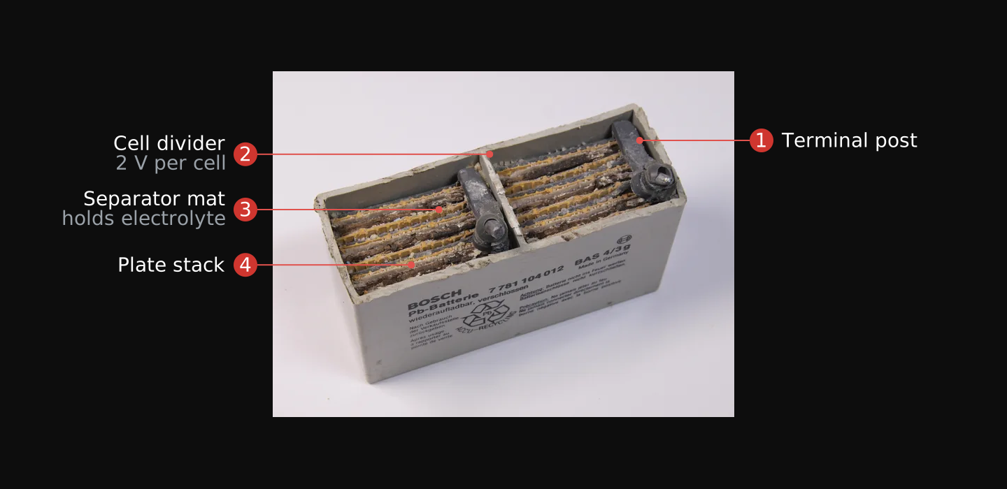
- The terminal post rises from the plate group; every conductor and load connection lands here.
- Each cell divider separates one 2-volt cell; six in series make the 12-volt block.
- The separator mat between plates holds the electrolyte, which is what makes the sealed block spill-proof.
- The plate stack is the lead plates themselves; thick plates mark a deep-cycle build, thin plates mark a starter.

Know which of the two builds you are holding, because they are made for opposite jobs. A starter battery, the car kind, has thin plates for maximum cranking current, and the battery handbook is blunt about its limit: a starter is not built for deep cycling, and deep use wears it out fast.9 A deep-cycle battery, the scooter, scrubber, or boat kind, has thick plates for repeated discharge.9 A free starter battery will run a bench if you draw it gently, but when you have the choice, take the deep-cycle block.
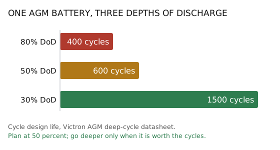
How deep you draw a battery sets its cycle life. Cycle life is stated per depth of discharge, never as one number. Battery University rates a deep-cycle block at 150 to 200 cycles at full discharge, 400 to 500 at 50 percent, and 1,000 or more at 30 percent.11 Victron's AGM datasheet runs the same curve on its own product: 400 cycles at 80 percent discharge, 600 at 50, and 1,500 at 30.12 The 80 percent figure is the deep end of that curve, a trade of battery life for capacity per cycle, not a safety ceiling and not a free allowance. Trojan, a deep-cycle maker, states the working rule: 80 percent discharge is the maximum, 50 percent or less is recommended, and shallow discharges give a longer battery life.13 So the bank is planned at 50 percent. A 100 amp-hour block holding 1,200 Wh on its label gives you 1,200 × 0.5 = 600 Wh to plan with. You draw deeper only for a job that justifies the shorter battery life.
A battery also loses charge just sitting, and the rate of that self-discharge depends on how it was built. The handbook names the mechanism: batteries with antimonial lead grids lose charge on the shelf much faster than those built on calcium-lead grids.9 A modern sealed block is the second kind; Victron rates its VRLA batteries, built on lead-calcium grids, at less than 2 percent per month at 20°C, doubling for every 10°C rise.12 So a find that drains in weeks has antimonial grids or damage, not a normal lead-acid rate. Two handbook rules apply at the curb. Never store a lead-acid battery discharged, because standing discharged promotes sulfation, a permanent loss of capacity and life.9 And do not condemn a find too fast, because batteries discarded as dead can often be restored with a long, slow recharge, three to four days at 2 to 3 amps for a starter battery.9
Test every find before you build on it, with the meter and a clock, in this order:
- Inspect the case. A crack, a bulged side, or a leaking post is grounds to reject the find on sight; everything after this step assumes an intact battery.
- Read the resting voltage. A healthy 12-volt block at rest reads about 12.3 to 12.75 volts.9 A reading far below that is a discharged battery, not yet a dead one.
- Recharge a low find slowly, in a ventilated space. Batteries discarded as dead can often be restored with a long, slow recharge, three to four days at 2 to 3 amps for a starter battery.9 A charging lead-acid battery gives off hydrogen gas, explosive in air from 4.1 percent.24 Make and break every connection away from the battery posts so any spark happens away from any gas.25 A sealed AGM block vents only on overcharge or cell failure,12 but the rule applies to every lead-acid charge.
- Rest it, then read again. A resting reading tracks the true state of charge only after the battery has sat unused: for the sealed family, accurate to within 20 percent after a day's rest and within 5 percent after five days.9 A block that will not hold its resting voltage after a full slow charge is scrap.
- Prove the capacity with a timed load. Put a measured load on the block, log the voltage every hour, stop at your planned depth of discharge, and multiply the load's watts by the hours it ran.3 That figure, not the label, is the battery's capacity in every later plan.
The connection between the battery and a load uses heavier wire than Module 03's signal circuits: a working load at 12 volts draws amps, not milliamps, and the wire is sized to that current; ten amps calls for 14-gauge.20 The leads land on the posts as ring terminals crimped onto stranded wire. The crimp technique is the same one Module 03 taught, but the crimper is a ratcheting tool sized for the terminal, and the terminal is a ring lug, not a pin or barrel splice. Unit 09 sizes every conductor in the full bank build.
Pull the sealed battery from one dead UPS and run steps 1 and 2 on it. Module 04's teardown method opens the box; the battery unplugs and lifts out.
Verify: the battery is out, inspected, and its resting voltage is written down with the date. If it reads low, steps 3 and 4 are this week's bench work.
This tier has a floor and a ceiling. Below it sits the 18650 cell from Module 03, right for a sensor or a node and the wrong scale for hundreds of watts. Above it sits the electric-vehicle traction pack, excluded for hazard rather than capacity. Electric, hybrid, and plug-in hybrid vehicles carry high-voltage battery systems of 200 to 800 volts, and stored energy remains after the pack is disconnected.14 The safe procedures are the manufacturer's own, verified with a rated voltmeter.14 The traction pack is a different hazard class from anything else here, and the Techno Guerrilla series does not train high-voltage work. Leave the pack in the wreck.
Salvaged LiFePO4
Your second source is LiFePO4 (lithium iron phosphate), and it is not Module 03's lithium. Module 03's lithium is the cobalt family, LiPo pouches and 18650 cells: 3.6 volts nominal, 4.2 volts full, energy-dense and volatile. A LiFePO4 cell runs 3.2 volts nominal and 3.65 volts full, four cells in series make the 12-volt-class pack, and its discharge curve is flat, holding near nominal across most of the discharge. It tolerates abuse the cobalt chemistries do not, and its cycle life is why it belongs in a bank: a maker's figure runs over two thousand charge cycles where an ordinary lithium cell is rated for roughly three hundred to a thousand.15 What does not carry over is the charging numbers; this chemistry has its own, and Unit 10 holds them.
You find LiFePO4 in e-bike packs, solar storage packs, portable power stations, and some cordless-tool lines, in the same discard stream Module 04 taught you to work. The power station is the clearest case: EcoFlow’s current Delta-class units state the chemistry on the spec sheet, LFP (LiFePO4 battery), with a published cycle life of 4,000 cycles to at least 80 percent capacity,27 so a discarded 2020s power station is a LiFePO4 pack in a case with its charger already around it. The market also sells a drop-in replacement: a lead-acid-shaped 12-volt case with LiFePO4 cells and a BMS (battery management system) inside, charging at 14.2 to 14.6 volts with a 13.4 to 13.8 volt float. Battle Born’s 100 amp-hour block lists at $799 in 2026.28 That price is why this unit is a salvage unit: the same chemistry comes out of a discarded power station or e-bike pack for the work of testing it.
| Property | Lead-acid (VRLA/AGM) | LiFePO4 |
|---|---|---|
| Nominal cell voltage | 2.0 V, six cells to a 12 V block | 3.2 V, four cells (4S) to a 12 V-class pack |
| Full cell voltage | about 2.05 to 2.125 V | 3.65 V |
| Discharge curve | voltage sags as it empties | flat near nominal, then drops fast |
| Planning depth of discharge | 50% | 80% |
| Cycle life | 400 at 80%, 1,500 at 30% | 2,000 and up, to 4,000 |
| Energy density | 30 to 40 Wh/kg | much higher for the same weight |
Keep a working pack whole. Its cells are matched and its BMS already carries the protection, so you use its own connector and never draw more current than its rating allows.16 The BMS is not optional equipment: a multi-cell lithium bank never runs without one, because the board balances the cells on charge, cuts the discharge at the first cell to reach its low-voltage limit, and trips on a short or an overload.15 The same board is also why you do not condemn a dead pack too fast. It cuts the pack off at its own limits, so a pack that reads zero at its connector can be a tripped protection board with good cells behind it, and only testing tells you which.15
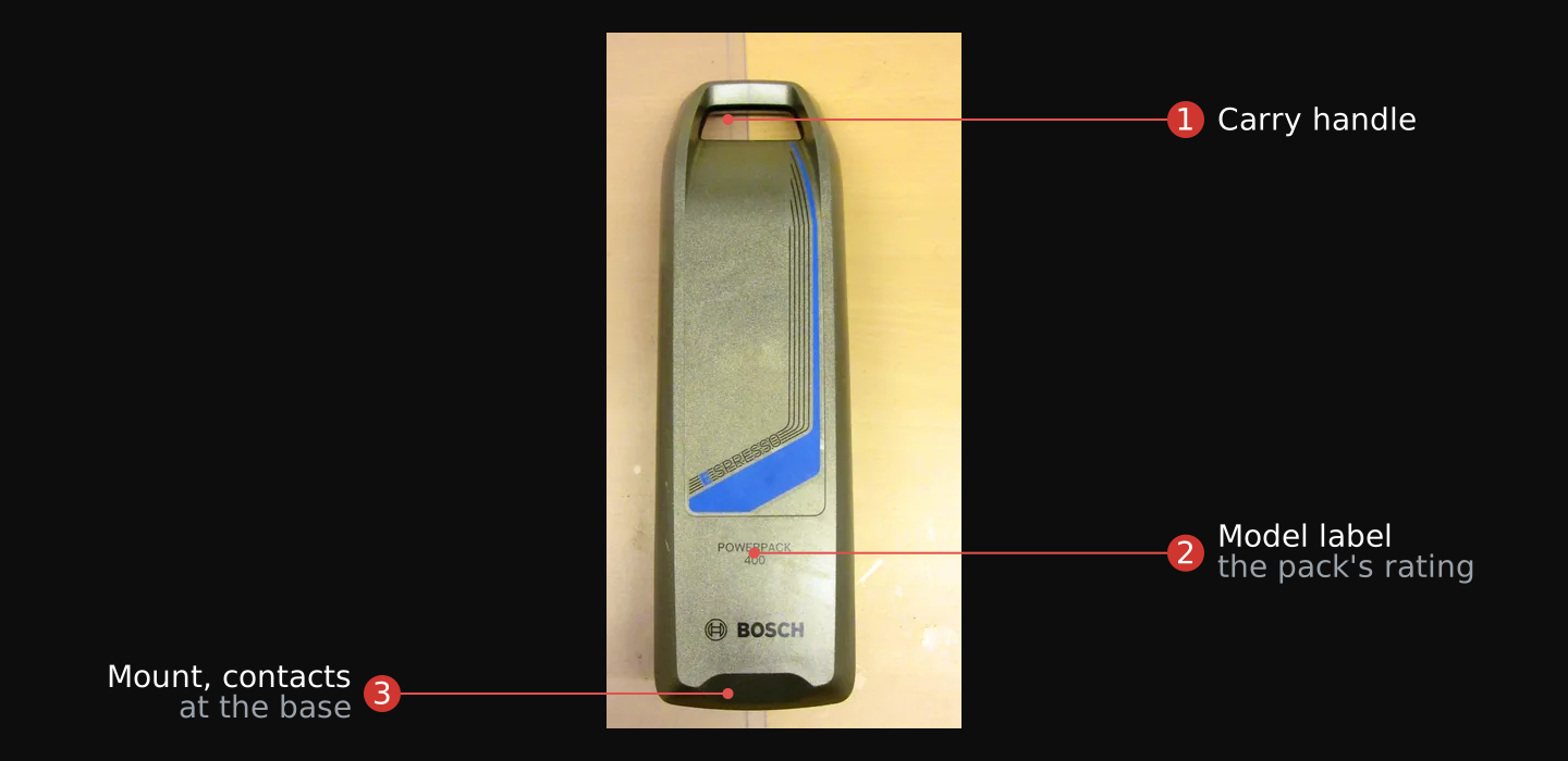
- The carry handle shows the pack detaches and carries; the detachable pack is the form found in the discard stream.
- The model label states the rating: voltage, watt-hours or amp-hours, and the series count behind them.
- The mount and contacts at the base are the pack's own connector; testing and loading run through it, never around it.

Test a salvaged pack the way Module 04 tests any pull, at the pack's own terminals first, with the watt-hour arithmetic from Unit 01:
- Read the pack at its own connector. Multimeter on DC volts, probes on the output terminals, nothing else connected.
- Divide by the series count. A 4S LiFePO4 pack reading 13.2 volts is sitting at 3.3 volts per cell, inside the healthy band between 3.2 nominal and 3.65 full. A per-cell figure near the bottom of the band is a discharged pack; charge it on the right profile before judging it.
- Treat a zero reading as a question, not a verdict. The BMS opens the circuit at its own limits, so zero at the connector can be a tripped board over good cells; only opening the pack settles it, and the pack stays whole until the reading forces the question.15
- Prove the capacity through the pack's own connector. A measured load within the pack's rating, a clock, an hourly voltage log: watts times hours is the tested capacity, the same arithmetic as the lead-acid bench.3 16
Run steps 1 and 2 on any lithium pack you own, a tool pack or an e-bike battery, and write down the per-cell figure next to the pack's label voltage. If you do not own a lithium pack yet, read the label on a cordless-tool battery or a power station at a store: take the rated voltage, work out the series count from the chemistry's nominal cell voltage, and write down the per-cell figure. The arithmetic is the skill; the pack comes later from the salvage stream.
Verify: a dated per-cell voltage, and the series count that produced it. If the connector reads zero, step 3 is your finding, not a failure.
The charging difference is the one that damages equipment. A LiFePO4 pack replacing lead-acid charges at about 14.4 volts absorption and 13.6 volts float for a 4S battery. The controller charging it must be set to its lithium profile rather than lead-acid, with equalization disabled and temperature compensation off. When in doubt, ask the battery's manufacturer for the recommended charge profile.17 Unit 10 states the full charging rule, with the temperature and current limits that go with it. Until then, never hang a salvaged pack on a controller still set to another chemistry's profile.
Build the bank
A field guide translated from a Ukrainian FPV drone unit states the conclusion directly: generators are demasking through noise and heat, and clustered people and vehicles around a power source make a target worth the munition.32 Marc Gonsalves, an American contractor held by FARC in the Colombian jungle for five years, described the camp generator as audible alongside the ordinary jungle sounds.33 A signature-management guide called EPEMCON disperses generators because clustered generators compound into a single target. It gives 300 feet as a workable distance, with each one masked against visual, thermal, and radar detection.31 The guide prescribes replacing generators with large battery accumulators, two or three per unit, and dispersing them.32 The bank you build here is that accumulator. The bank is Module 03's series-parallel physics applied to whole batteries: series raises voltage, parallel raises capacity, and parallel requires matched voltages before joining. At this scale, the physics becomes five rules:
- Pick the system voltage and hold it. Everything in this module runs at 12-volt class, because the loads take it directly: the light, the radio, the Starlink DC supply.4 Two 12-volt blocks in series make 24; nothing here needs it.
- Run blocks in parallel for capacity, matched first. Two 100 amp-hour blocks in parallel are a 200 amp-hour bank at 12 volts. Before the jumper lands, both blocks read nearly the same resting voltage, or current flows from the fuller block into the emptier one through bare cable.
- Never mix chemistry or age on one bank. One bank, one chemistry, one charge profile: a lead-acid block and a LiFePO4 pack cannot share a bus, because no controller setting is right for both.17 And a worn block in a parallel bank limits the bank to its own capacity; batteries of visibly different age or tested capacity run as separate banks.
- Fuse every branch at the battery positive. The electrical code states the rule: conductors are protected against overcurrent in accordance with their ampacities,18 so the fuse is rated to the wire and blows before the wire overheats. The fuse maker adds a margin: a fuse should carry no more than about three-quarters of its rating in normal use, so a 0.7-amp branch gets
0.7 ÷ 0.75 ≈ 0.9, the next standard size up, 1 amp.19 - Size the wire to the current, and land every negative on one bus. A couple of amps runs on 18-gauge; ten amps needs 14-gauge.20 One common ground gives the meter, the loads, and the controller a single reference.
The working hazard at 12 volts is current, not shock. A shorted lead-acid block drives heavy current through whatever bridges its posts. Do not wear rings, metal wrist bands, or a watch when working at the posts,51 keep tools insulated or off the top of the battery, and never lay anything metallic across the terminals.
Wire has a second limit besides the current it can carry: length. A run loses voltage over both conductors, out and back, in proportion to the current and the length. Victron's wiring guide advises aiming for a voltage drop no bigger than 2.5 percent, which on a 12-volt system is 0.3 volts.30 A long run to a far load or a distant panel therefore takes a heavier gauge than its current alone requires. Prove it with the meter: read the voltage at the battery and again at the load under load, and the difference is the run's drop.
The small loads of the site draw from the same bank. A sensor, an alarm panel, or a controller board at 5 or 9 volts does not get its own battery; it feeds from the 12-volt bus through the buck converter Module 03 taught, on its own fused branch like any other load. The exception is a device that must run detached from the site, a standalone sensor placed away from the bank, which stays on Module 03's cell tier. Everything that lives at the site draws from the bank, so one charge system maintains everything.
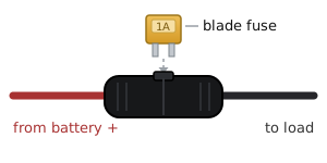
None of this needs solder. Battery posts take ring terminals crimped onto stranded wire sized to the draw, or the clamps the find came with. The inline fuse holder splices into the positive wire with the crimp joints Module 03 taught, and a controller's terminals are screw clamps. Strip, land, tighten, tug-test.
Conceal the finished bank by Module 04's method: a case or a floor void. Keep ventilation open for anything lead-acid that charges there; charging produces hydrogen.24 Status LEDs and controller displays give off light; tape covers them. Keep the DC runs short and the converters few and away from antennas, so conducted noise couples onto the least wiring.
The last step of the build is proof. Put the measured load from Unit 06 on the bank, log the voltage every hour, and run it to your planned depth of discharge. The computed runtime is usable watt-hours divided by the load's watts, and the log either confirms it or gives you the bank's true capacity, which replaces the label in every later plan. Unit 11 turns that log into the bank's monitoring baseline: the full-and-rested voltage, and the readings every later health check is judged against. Testing under the real load matters for one more reason: a battery delivers less than its rated amp-hours as the discharge rate rises, the handbook's Peukert relation,9 and a proof run at your own load captures that automatically.
Charging and solar
A bank is charged to a charge profile, the voltage pattern belonging to its chemistry, and a mismatched profile is the fault that wrecks salvaged equipment. Lead-acid VRLA charges on a multi-step curve, a constant-current bulk phase followed by constant-voltage absorption and float phases.12 A LiFePO4 pack replacing it charges at about 14.4 volts absorption and 13.6 volts float for a 4S pack, on the controller's lithium profile, with equalization disabled and temperature compensation off; when in doubt, ask the battery's manufacturer for the recommended charge profile.17 Equalization is a deliberate lead-acid overcharge that lets the voltage rise uncontrolled to balance the cells,9 so left enabled on a lithium pack it becomes a scheduled overvoltage. Set the profile before anything connects, every time.
| Setting | Lead-acid (VRLA/AGM) | LiFePO4 (4S) |
|---|---|---|
| Absorption voltage | maker's figure, near 14.5 to 14.9 V | about 14.4 V |
| Float voltage | 13.6 to 13.8 V | about 13.6 V |
| Equalization | a lead-acid maintenance step | disabled, always |
| Temperature compensation | on | off |
| Charge-current ceiling | finish at 5 A per 100 Ah | 0.5C, gentler at 0.2C |
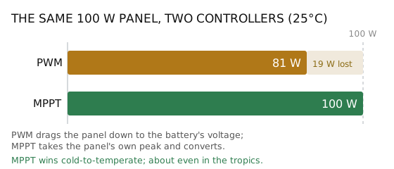
Where mains power is usually up, the UPS box from Unit 07 is already the charger: it holds its battery on the constant-voltage float charge that standby service calls for.9 The architecture scales from that one box to any mains charger with the right profile, and the bank carries the site when the mains is down. Off-grid, the source is a solar panel through a charge controller, and controllers come in two kinds. A PWM controller is in essence a switch connecting the panel to the battery, which pulls the panel down to near the battery's voltage whether or not the panel produces its best power there. An MPPT controller adjusts its own input voltage to draw the panel's maximum power, then converts it to the voltage and current the battery's chemistry requires.21 Victron's worked example quantifies the gap: at 25°C the same 100-watt panel delivers 81 watts through PWM and the full 100 through MPPT, and MPPT is generally accepted to outperform PWM in cold to temperate climates, the two running about even in subtropical to tropical ones.21 The difference matters most with salvage, because a found panel's voltage was never chosen to match your bank, and an MPPT controller handles that mismatch and still delivers the panel's full power.
A charge controller comes from the same salvage stream as the battery. A dead garden solar kit, an RV with a failed battery, or an off-grid setup with damaged panels often carries a working controller that outlasted the rest of the system. Bought new, a PWM controller is the low-cost solution for a small system;21 an MPPT costs more but pays back on mismatched salvaged panels.
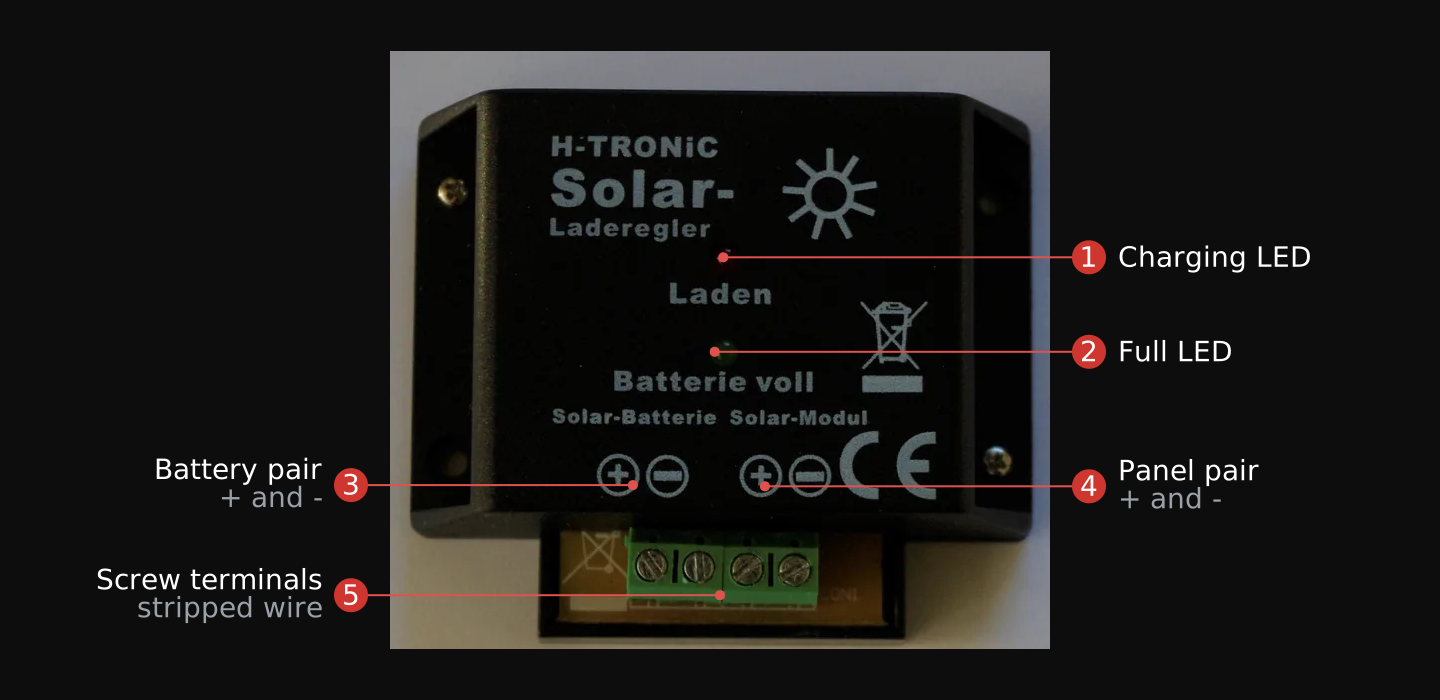
- The charging LED lights while the panel charges the battery: the first thing checked in sun.
- The full LED lights when the controller holds the battery at float.
- The battery pair is where the bank lands, positive through the main fuse.
- The panel pair takes the panel's two leads, polarity checked before they land.
- The screw terminals take stripped wire under a screw: no solder anywhere in the build.

Temperature and current bound the charge as tightly as voltage does. Never charge a lithium pack below freezing: charging lithium cells below 0°C damages or destroys them, because lithium metal collects permanently on the anode, cutting capacity and raising the risk of the cell catching fire after an impact.15 A cold pack comes indoors and warms to at least 10°C for a few hours before it charges, and a colder battery always takes a lower charge current.15
Current has its own ceiling: most lithium cells carry a charge rating of not more than about 0.5C, and charging closer to 0.2C is much better for the cell's health.15 The C-rate reads off the pack's amp-hour figure, so a 5 amp-hour pack at 0.5C charges at 5 × 0.5 = 2.5 amps.15 Check the charger's output current against the pack's charge rating before it connects, the same way the profile is checked.
Lead-acid charge current follows a different pattern. On a constant-voltage charger the battery pulls a high current early, capped by the gassing voltage of about 2.4 volts per cell, and that current decays on its own as the charger holds the voltage. The finishing charge then runs at a constant current no higher than 5 amps per 100 amp-hours of capacity.9 A charger with the right profile carries this regulation for you, which is one more reason the profile, not the charger's size, is the setting that matters.
A charging lead-acid battery gives off hydrogen gas, explosive in air from 4.1 percent.24 The DOE handbook's rule: provide adequate ventilation whenever charging is in progress, and allow no smoking, electric sparks, or open flames near a charging battery.25 Make and break every connection away from the battery posts so any spark happens away from any gas. A sealed AGM block vents only on overcharge or cell failure,12 but the ventilation rule applies to every lead-acid charge regardless of construction.
The panel is sized from Unit 06's daily budget, with the solar figure looked up rather than guessed. NREL's PVWatts calculator returns your location's daily solar resource, its peak sun hours;22 divide the daily watt-hour budget by that figure, then by 0.7 for system losses, and you have the panel wattage that replaces one day's use.3 The controller is sized from the panel's short-circuit current, Isc, printed on its label: its current rating stands above the panel's Isc with margin, the working notes' rule being Isc times 1.25.23 A smaller salvaged panel than the arithmetic requires still works; it replaces less energy than you draw, so the bank drains over days instead of holding level, and your log shows exactly that.
Run the setup in this order, and verify the charge with the meter at the end:
- Set the chemistry profile first, with nothing connected, and check it against the battery maker's figures: for a 4S LiFePO4 pack, about 14.4 volts absorption and 13.6 float, equalization disabled.17 For the sealed lead-acid family, the maker's own absorption and float figures.12
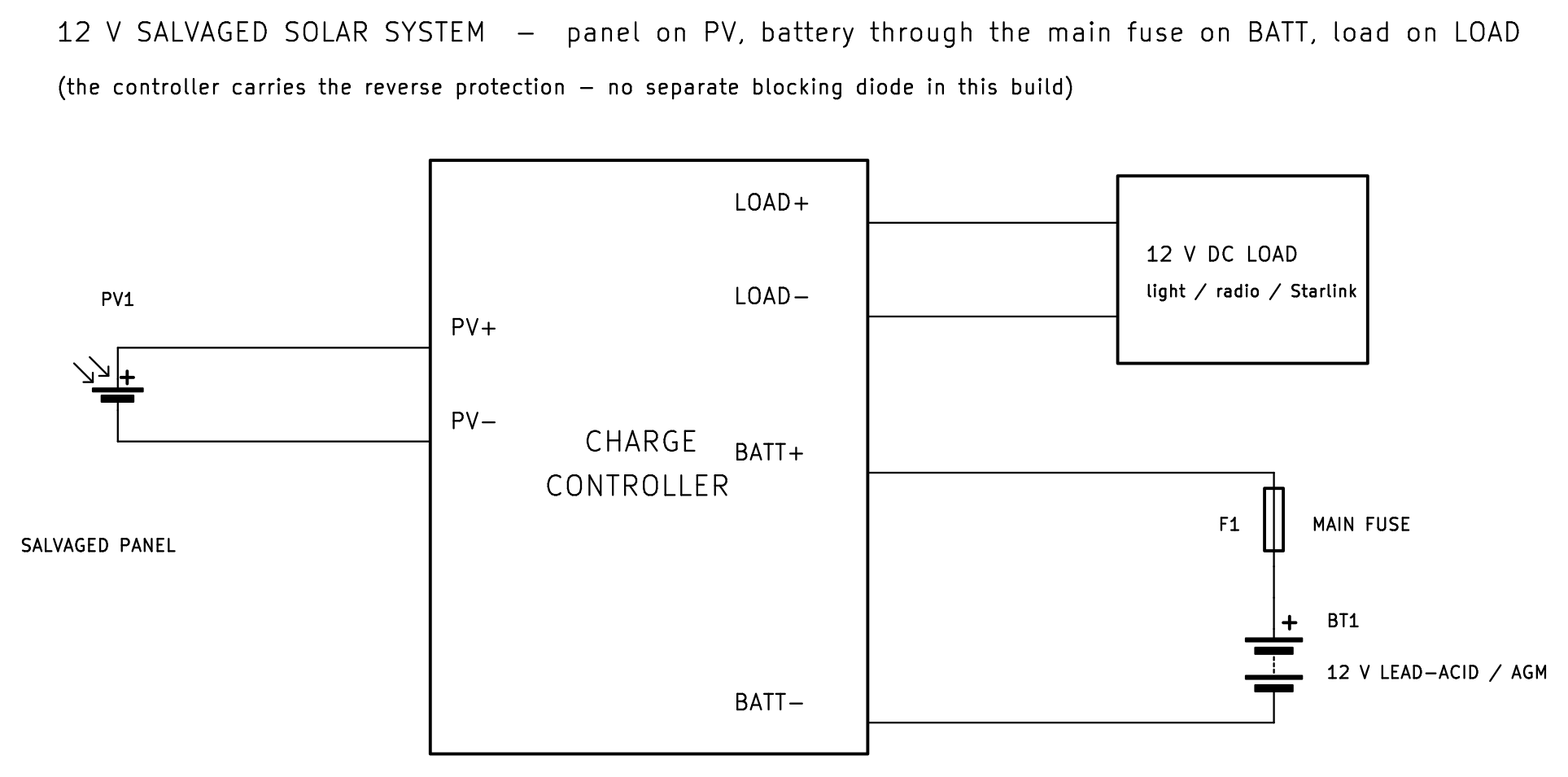
- Land the bank on BATT, the positive through the main fuse from Unit 09, the negative to the common bus.
- Land the panel on PV, both leads, polarity checked with the meter before they land.
- Land the load on LOAD, or on the battery bus through its own fuse if the controller has no load terminals.
- Prove it is charging with the meter. In sun, the voltage across the bank climbs to the profile's absorption figure and holds, then falls back to float; a bank that never reaches absorption is a panel, wiring, or profile problem, found in that order.12
Set your charger or controller to the chemistry of the battery you tested in Unit 07 or 08. The UPS box from Unit 07 float-charges lead-acid on mains; a solar controller is set by hand and charges either chemistry from a panel. Connect the battery and watch the charge with the meter across the terminals.
Verify: the measured voltage tops out at the profile's absorption figure for your chemistry, then drops to float. A number that keeps climbing past it means the profile is wrong; disconnect and re-check the setting.
Bank monitoring and troubleshooting
A resting lead-acid battery shows its state of charge in its open-circuit voltage. Battery University's reference for a 12-volt starter battery: 12.65 volts at 100 percent, 12.45 at 75, 12.24 at 50, 12.06 at 25, and 11.89 at zero, read at 26°C after a 24-hour rest.29 The rest matters more than the tenth of a volt: accurate readings require the battery to sit in an open-circuit state for at least four hours, and battery manufacturers recommend 24 for lead acid.29 A bank under load or fresh off the charger reads high or low of its true state, so take the routine reading before the day's charging starts. Trojan's full-charge figure for its 12-volt deep-cycle blocks runs slightly higher, 12.73 volts,13 so learn your own bank's full-and-rested number during the Unit 09 proof and judge later readings against it.
- 100 percent12.65 V at rest, 26°C
- 75 percent12.45 V
- 50 percent12.24 V, the lead-acid planning floor
- 25 percent12.06 V, past the plan; recharge now
- 0 percent11.89 V, standing here costs capacity for good
The routine that keeps the bank serviceable is a monthly check. Trojan tells its flooded-battery customers to check once a month until the watering pattern is known.13 The bank's log follows the same rhythm: the resting voltage against the table above, the terminals for corrosion and tightness, the case for cracks or bulging, and the log updated with the date and the reading. A bank in storage gets the same reading on the same cadence, with Trojan's storage rule as the trigger: a stored battery gets a boost charge when it shows 70 percent charge or less.13 A LiFePO4 pack is the exception to reading voltage, because its flat discharge curve makes voltage a poor gauge across the middle of its range; its BMS tracks the pack's state, so read the pack's own indicator where it has one and treat the meter reading as a full-or-empty check.
Cold changes what the bank holds. Low temperatures cut a battery's capacity, though they lengthen its life in float or storage,25 so a bank sized in warm weather carries fewer watt-hours in winter. Prove the runtime at the temperature the site will run at, and date the log so the seasons stay comparable.
When something is wrong, work from the symptom, with the meter and the log:
- The bank never reaches absorption voltage. Check the panel, wiring, and profile in that order: panel voltage at the controller's PV terminals, then every joint on the charge path, then the profile setting against the battery maker's figures.12 17
- The bank charges but drains overnight with the loads off. Read the branch fuses one at a time: a branch that still draws with its device off is the leak. A bank that drains with every branch pulled is a battery problem: one worn block limiting a parallel bank's capacity, found by resting-voltage readings on each block separately.
- A fuse blows more than once. The fuse is doing its work: the branch draws more than its wire was sized for, from a fault in the device or a short in the run. Find the draw with the meter before any fuse goes back in; the fuse is rated to the wire, and a larger fuse only moves the failure into the wire.19
- A block runs warm on charge, or the sealed case bulges. Overcharge: the profile or its voltage setting is wrong for the chemistry, and a VRLA block vents only on overcharging or cell failure.12 Disconnect the charge source, re-check the profile, and re-read the block rested before putting it back in the bank.
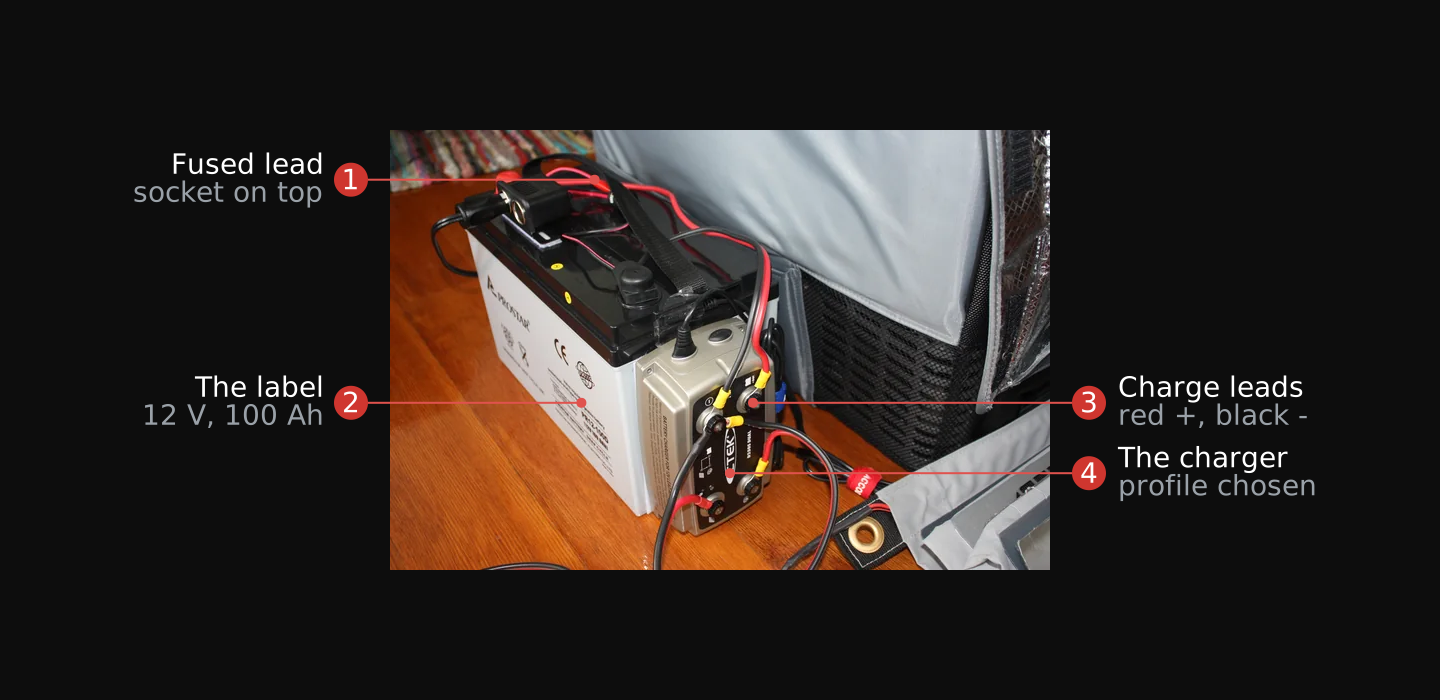
- The fused lead gives the accessory socket its own fused positive branch, the Unit 09 rule applied.
- The label states the rating: 12 V, 100 Ah, deep-cycle VRLA, the bank tier of Unit 07.
- The charge leads run red to positive, black to negative, clamped at the posts.
- The charger is a lead-acid charger on its lead-acid battery; the profile is checked before the clamps land.

Take the resting voltage of the battery you tested in Unit 07, after it has sat off the charger and off any load overnight, and place it on the table above.
Verify: a dated log line with the resting voltage and the state of charge it maps to. This line, repeated monthly, is the bank's health record.
Field exercise
Task: Read one building's electrical system from open sources to the panel and compute the headroom on one branch circuit. Build one battery bank from salvaged batteries and power a measured load from it to prove the runtime.
Condition: Given your own residence or a structure you have permission to assess, open-source tools (OpenStreetMap, Overpass Turbo, utility outage maps), a multimeter, a clamp meter, salvaged batteries (lead-acid/AGM and/or LiFePO4), fuses, holders, wire sized to the current, and a charge controller or charger. Work only in structures you have the right to assess and with batteries you have every right to take. Charge lead-acid only in a ventilated space.
Standard: Record two dated products on the completed field exercise worksheet.
- Structure assessment. Name the serving utility from open sources (Unit 02). Identify the service type as overhead or underground (Unit 03). Read the main disconnect rating at the panel, or record the exterior reads from Units 02 and 03 if the panel is inaccessible (Unit 04). Compute one branch circuit's headroom: 80 percent of the breaker rating minus the clamp-meter reading on that circuit's existing draw (Unit 04). Identify a tap point on that circuit (Unit 05). The tap itself is optional where you do not own the structure.
- Battery bank. Measure each battery's resting voltage and test its capacity under a real load (Units 07 and 08). Measure the load in watts:
V × I = W, from your own meter (Unit 06). Prove the computed runtime against the observed runtime to your planned depth of discharge (Unit 11). Fuse every battery-positive branch (Unit 09). Set the charge source to the bank's chemistry profile before connection (Unit 10). The build is Quiet: no generator, no exposed light, no heat or interference tell (Unit 09). Solar charging is not required to complete this exercise.
Download the field exercise worksheet (PDF)
The assessment and the bank transfer to any structure you operate from. A new site gets the same pass: open-source read, exterior read, panel read, headroom computation. A new load gets measured on the bench, sized against the bank, and logged the same way. The worksheet is the baseline; a later assessment at the same structure is measured against it.
The in-person course runs this module's build at clinic scale: the field medic's suction, exam light, monitor, and comms hang off the same bank architecture with bigger blocks and more panel, and the power log is part of the site's handover record. The parts are larger; the procedure is the same.
Module test
Task: Complete the Module 05 test.
Condition: Given ten questions covering units one through eleven, without reference to the module units or notes.
Standard: Answer at least eight of ten questions correctly. For each question missed, reread the unit named in the feedback and retake the test until the standard is met.
Glossary
- AFCI (arc-fault circuit interrupter)
- A breaker that de-energizes the circuit when it detects an arc fault, protecting the wiring against arcing.
- AGM (absorbent glass mat)
- A sealed lead-acid construction in which a porous microglass mat holds the electrolyte, so the battery works in any orientation without spilling.
- BMS (battery management system)
- The board inside a lithium pack that balances the cells on charge, cuts discharge at the low-voltage limit, and trips on a short or overload.
- Branch circuit
- A circuit from the panel's breaker to the outlets, lights, or appliances it feeds; its breaker rating is the circuit's ceiling.
- C-rate
- A charge or discharge current stated as a multiple of the pack's amp-hour capacity; a 5 amp-hour pack charging at 0.5C takes 2.5 amps.
- Charge profile
- The voltage pattern a charger or controller applies, belonging to one battery chemistry; a mismatched profile damages the bank.
- Clamp meter
- A meter whose hinged jaw closes around one conductor to read the current it carries without breaking the circuit; the jaw is a current transformer.
- Cycle life
- The number of charge-discharge cycles a battery sustains, stated per depth of discharge; shallower cycles multiply it.
- Deep-cycle battery
- A lead-acid build with thick plates made for repeated discharge, as against the thin-plate starter battery built for cranking bursts.
- Depth of discharge (DoD)
- The fraction of a battery's capacity taken out before recharge; the planning figure for lead-acid is 50 percent.
- Equalization
- A deliberate controlled overcharge in lead-acid maintenance; it must be disabled when a lithium pack is on the controller.
- Fuse cutout
- A protective device on the primary side of a pole transformer; its hinged fuse holder drops open when blown, visible from the ground.
- GFCI (ground-fault circuit interrupter)
- A device that disconnects the circuit when the current on the hot and neutral do not match, indicating a leak through a person or ground path.
- Headroom
- The spare capacity on a branch circuit, computed as 80 percent of the breaker rating minus the measured draw, that a tap can use without tripping the breaker.
- Isc (short-circuit current)
- The most current a solar panel can produce, printed on its label; the controller's rating stands above it with margin.
- LiFePO4
- Lithium iron phosphate: a lithium chemistry at 3.2 volts nominal and 3.65 full per cell, flat discharge curve, long cycle life, distinct from the cobalt lithium of Module 03.
- Main disconnect
- The single breaker or switch that cuts all power to the panel; its amperage rating is the ceiling on everything the building draws at once.
- Masthead
- The fitting at the top of a service mast that keeps moisture out where the overhead service conductors enter the conduit; also called a gooseneck or weatherhead.
- Meter socket
- The fixed enclosure on the wall or pole into which the utility meter plugs; the socket is the permanent half and the meter the removable one.
- MPPT (maximum power point tracking)
- A controller type that adjusts its input voltage to draw the panel's maximum power, then converts it to the voltage and current the battery's chemistry requires.
- Peak sun hours
- A location's daily solar resource expressed as equivalent full-sun hours, looked up in NREL's PVWatts calculator.
- PWM (pulse-width modulation) controller
- A controller type that switches the panel onto the battery, pulling the panel to near battery voltage.
- Self-discharge
- Capacity lost on open-circuit stand; its rate depends on the grid construction, antimonial grids losing far faster than calcium-lead.
- Service drop
- The overhead conductors from the last pole to the building's service-entrance point; the underground equivalent is a service lateral.
- Service lateral
- The underground conductors from the street main to the first point of connection at the building; the overhead equivalent is a service drop.
- Service point
- The point of connection between the utility's facilities and the premises wiring; everything upstream is the utility's, everything downstream is yours to read.
- Sulfation
- The permanent capacity loss a lead-acid battery takes from standing discharged.
- Tap
- A connection to a branch circuit that has headroom, made at a receptacle or a junction box, sized and fused for the draw it carries.
- VRLA (valve-regulated lead-acid)
- The sealed lead-acid family, venting gas only on overcharge or cell failure; AGM and gel are its constructions.
- Watt-hour (Wh)
- The energy measure comparing any battery to any load: volts times amp-hours for the battery, watts times hours for the load.
Sources
- “Mission Critical Radio and You,” Volume I, Light Fighter Manifesto (Light Fighter Library, LFM Publications): the remote-base requirement that “via solar power and auxiliary batteries, the system will remain on the air in the event of failure of the electrical grid.”
- “Kamikaze FPV Drones,” Volume III, Light Fighter Manifesto (Light Fighter Library, LFM Publications): “Power Supply is one of the most significant limitations of sustained drone operation. Some regeneration methods include larger batteries, like a car battery or LiFePo4, generators, and the apparent outlet.”
- Unbound Solar, “Battery Bank Sizing”: watt-hours per day = watts × hours, amp-hours = watt-hours ÷ voltage, usable depth of discharge of about 80 percent for lithium and 50 percent for lead-acid, and sizing a bank and its days of autonomy against the daily load. unboundsolar.com (verified 2026-07-08).
- Starlink, Standard DC-DC Power Supply specification sheet: “Input 12-48VDC 30A,” “Output 56V 3.57A,” “IP66 Type 4,” operating −40 to 60°C; the Standard dish runs DC-native from a 12 V battery system through this supply, with no inverter. starlink.com (re-verified from the current spec sheet 2026-08-11; the 2026-07 support-article URL is dead).
- Schneider Electric (APC), UPS battery service life (three to five years): a dead UPS is usually a failed sealed-lead-acid battery rather than failed electronics. apc.com (re-verified 2026-08-11: “Most APC batteries should last three to five years”).
- Pull-A-Part, “FAQ”: the self-service pull salvage-yard model; “our standard admission fee is $2,” “Pull-A-Part accepts cash and major credit cards,” and “you need to bring your own tools.” pullapart.com (re-verified 2026-08-11 at the current FAQ URL).
- Fullriver Battery, Mobility applications (battery maker): mobility scooters and power chairs run on sealed, spill-proof deep-cycle AGM batteries, a 12 V product line built with thick lead plates that “can be recharged hundreds of times.” fullriverbattery.com (verified 2026-07-09).
- Trojan Battery, Floor Machine Batteries (deep-cycle battery maker): a complete range of deep-cycle batteries for floor cleaning machines, from flooded lead-acid to AGM, in 6 V and 12 V sizes. trojanbattery.com (re-verified 2026-08-14 at the current URL; the 2026-07 URL is dead).
- David Linden and Thomas B. Reddy, eds., Handbook of Batteries, 3rd ed., McGraw-Hill, 2002 (Light Fighter Library, Field-Craft/Energy-Tech), chapters 3, 6, and 22–24: the radio-transceiver duty-cycle sizing case (“changing loads from receive to transmit in the operation of a radio transceiver,” with the military-transceiver example of a 1 A transmit load, 50 mA receive load, 9:1 receive-to-transmit duty cycle); the equalization charge, “the normal recharge is extended… allowing the battery voltage to rise uncontrolled”; lead-acid energy density “typically 30–40 Wh/kg”; the open-circuit cell voltage of 2.05 to 2.125 volts (12.3 to 12.75 volts for six cells, this module's multiplication); the VRLA family and the absorbed-glass-mat construction whose immobilized electrolyte “allows batteries to operate in different orientations without spillage”; SLI batteries built with thin plates, with “SLI batteries are not designed for deep-cycling service, and very short lives are generally obtained with such operation,” against deep-cycling designs built with “thick plates with high paste density”; self-discharge “more severe with batteries which use antimonial lead grid alloys in the positive plates,” minimized on calcium-lead nonantimonial grids; storing cells “in a discharged condition promotes sulfation and decreases capacity and life”; and “often batteries discarded as dead can be restored with a long, slow recharge (3 to 4 days at 2 to 3 A for SLI batteries)”; and Peukert’s equation (ch. 3), capacity falling below the rated amp-hours as the discharge rate rises.
- Battery University, BU-214 “Summary Table of Lead-based Batteries”: specific energy 30–50 Wh/kg for starter batteries and 20–30 Wh/kg, some higher, for deep-cycle batteries; nominal cell voltage 2.00 V. batteryuniversity.com (verified 2026-08-11).
- Battery University, BU-201 “How does the Lead Acid Battery Work?”: deep-cycle cycle life by depth of discharge, 150–200 cycles at 100 percent, 400–500 at 50 percent, 1,000 and more at 30 percent. batteryuniversity.com (verified 2026-08-11).
- Victron Energy, Gel and AGM Batteries datasheet and general technical information: self-discharge “less than 2% per month at 20°C,” doubling for every 10°C increase, on lead-calcium grids; AGM cycle design life 400 cycles at 80 percent discharge, 600 at 50 percent, 1,500 at 30 percent; the three-step bulk/absorption/float charge curve; and VRLA valves venting gas only on overcharging or cell failure. victronenergy.com (verified 2026-08-11).
- Trojan Battery, Battery Maintenance (deep-cycle battery maker): “80% discharge is the maximum safe discharge,” “50% (or less) discharges are recommended,” and “shallow discharges will result in a longer battery life”; checking batteries once a month until the watering pattern is known; the 12.73 V full-charge open-circuit figure; and the storage rule that batteries “should be given a boost charge when they show a 70% charge or less” (maintenance figures re-verified 2026-08-11). trojanbattery.com (verified 2026-07-09).
- Canadian Centre for Occupational Health and Safety (CCOHS), “Battery Safety — High-Voltage Batteries in Electric, Hybrid, or Plug-in Hybrid Vehicles”: “Electric, hybrid, and plug-in hybrid vehicles have both high-voltage (200-800 volt) and low-voltage (12-volt lead-acid batteries) battery systems”; stored energy remaining after the high-voltage battery is disconnected; and verifying no high-voltage energy is present with a CAT voltmeter while following the manufacturer's instructions. ccohs.ca (verified 2026-08-11).
- Micah Toll, DIY Lithium Batteries: How to Build Your Own Battery Packs, 2017 (Light Fighter Library, Field-Craft/Energy-Tech): LiFePO4 rated for over two thousand charge cycles where an ordinary lithium cell is rated for roughly three hundred to a thousand, and the battery-management board's balance, low-voltage cutoff, and short/overload protection that a multi-cell bank never runs without. Also the charging temperature and current limits: “Charging lithium battery cells at low temperatures, below 0ºC, will damage or destroy the cell,” with lithium metal collecting permanently on the anode and an increased “risk of the battery cell catching on fire if it suffers an impact”; cold packs warmed “to at least 10ºC for a few hours” before charging, with “a lower charge current when charging colder batteries”; and the charge-rate ceiling, “not to charge most lithium cells at more than 0.5 C, and charging closer to 0.2 C is much better for the cell’s health,” the worked example being a 5 Ah cell at 0.5 C charging at 2.5 A.
- ToolGuyd, “Comparing Power Tool Battery Specs: Watt-Hours vs Amp-Hours”: an intact salvaged lithium pack keeps its own matched cells and BMS, used within its rating through its own connector. toolguyd.com (re-verified 2026-08-11 at the current URL: 1 Wh = 1 V × 1 Ah, packs built from matched cells with a battery management system).
- Lifeline Batteries, “How to Program BSE Charge Controllers for LiFePO4 Batteries” (battery maker): a charge controller charging a lithium battery must be set to the lithium profile, not lead-acid, with equalization disabled and temperature compensation off; LiFePO4 charging at about 14.4 V absorption and 13.6 V float for a 4S battery; and “ask the manufacturer for the recommended charge profile” when in doubt. lifelinebatteries.com (verified 2026-07-09).
- National Electrical Code (NFPA 70), §240.4 (protection of conductors in accordance with their ampacities) and §400.5 (flexible cord and cable ampacity), 2005 ed.
- Littelfuse, Fuseology Design Guide (fuse maker): the designer “generally loads the fuse not more than 75% of the nominal rating listed by the manufacturer,” and “fuses at room temperature should last indefinitely if operated at no more than 75% of nominal current rating.” littelfuse.com (re-verified 2026-08-11 from the current design guide; the 2026-07 URL is dead).
- PowerStream, wire gauge and ampacity chart: the current each wire gauge can carry; the gauge-to-amperage pairings here are a conservative reading of that chart for short 12 V branch runs. powerstream.com (verified 2026-07-08).
- Victron Energy, “Which solar charge controller: PWM or MPPT?” (technical note): “The PWM controller is in essence a switch that connects a solar array to the battery,” pulling the array's voltage down to near the battery's; the MPPT controller “will adjust its input voltage to harvest the maximum power from the solar array”; the worked example where the same 100 W panel yields 81 W through PWM against 100 W through MPPT at 25°C; and “it is generally accepted that MPPT will outperform PWM in a cold to temperate climate, while both controllers will show approximately the same performance in a subtropical to tropical climate.” victronenergy.com (verified 2026-07-09).
- NREL PVWatts Calculator: NREL's public tool returning a location's peak sun hours (annual-average daily solar resource) for sizing a panel array to a daily load; enter your own location for the figure that applies to you. pvwatts.nrel.gov.
- Guerrilla-Tech salvage and component working notes (SOLAR-SIZING), Light Fighter working library: sizing a charge controller's current rating above the panel's short-circuit current times 1.25. Stated here as the working-notes rule; the underlying code provision (NEC 690.8) was not re-verified against the code text for this module.
- Canadian Centre for Occupational Health and Safety (CCOHS), “Battery Charging — Industrial Lead-Acid Batteries”: when lead-acid batteries are being recharged they generate hydrogen gas, “explosive limits are 4.1 to 72 percent hydrogen in air,” and ventilation guidance limiting accumulation to 25 percent of the lower explosive limit, about 1 percent of the volume. ccohs.ca (verified 2026-08-11).
- U.S. Department of Energy, DOE Fundamentals Handbook: Electrical Science (Basic Battery Principles), DOE-HDBK-1011/2-92 (Light Fighter Library, Field-Craft/Energy-Tech): “since hydrogen is highly explosive, it is necessary to provide adequate ventilation to the battery whenever charging is in progress” and “no smoking, electric sparks, or open flames are allowed near a charging battery”; and low temperatures lowering battery capacity.
- National Electrical Code (NFPA 70), §702.2 (optional standby systems, definition) and §702.6 “Transfer Equipment,” 2005 ed.: transfer equipment “designed and installed so as to prevent the inadvertent interconnection of normal and alternate sources of supply.”
- EcoFlow, DELTA 3 Plus portable power station specifications: “Battery Chemistry LFP (LiFePO4 battery),” “Cycle Life 4000 cycles to 80+% capacity,” battery pack IP65 with BMS. ecoflow.com (verified 2026-08-11).
- Battle Born Batteries, 100Ah 12V LiFePO4 Deep Cycle Battery product page: a built-in BMS with “integrated protections,” marketed as “a straightforward upgrade from traditional lead-acid batteries” fitting common Group 27/31 compartments; charge 14.2–14.6 V, float 13.4–13.8 V; listed at $799.00 (regular $949.00). battlebornbatteries.com (verified 2026-08-11).
- Battery University, BU-903 “How to Measure State-of-charge”: the BCI open-circuit-voltage table for a 12-volt starter battery (12.65 V at 100 percent, 12.45 at 75, 12.24 at 50, 12.06 at 25, 11.89 at 0, “taken at 26°C (78°F) after a 24h rest”), and “the battery needs to rest in the open circuit state for at least four hours; battery manufacturers recommend 24 hours for lead acid.” batteryuniversity.com (verified 2026-08-11).
- Victron Energy, Wiring Unlimited (v2, August 2024), section 2.7 “Current, cable resistance and voltage drop”: “we advise aiming for a voltage drop no bigger than 2.5%,” the accompanying table putting the 12 V limit at 0.3 V; the drop is computed over both conductors and scales with current and run length. victronenergy.com (PDF fetched and read 2026-08-11).
- Signature Management EPEMCON SOP: A Guide to Reduce Technical Signature (Light Fighter Library, Intelligence/Threat-Analysis): generator clusters emit a greater EM signature; generators spaced at least 300 feet apart; multispectral netting “masking generators from visual, IR thermal, and radar sensors”; cardboard wrapped in tinfoil as an EM shield; generator defilade blocking “EM as well as visual, audible, and IR emissions.”
- Challenges for Operators During the Winter Period (translated field guide, Light Fighter Library, Intelligence/Threat-Analysis): “Generators are demasking (noise, heat)” as the cause of the targeting problem; prescribed fix: “Use large accumulators (EcoFlow, Bluetti) — 2-3 per unit” instead of generators; minimum 10–12 batteries per drone in winter; motors may not start below −15°C.
- Marc Gonsalves, Tom Howes, and Keith Stansell, Out of Captivity: Surviving 1,967 Days in the Colombian Jungle (New York: William Morrow, 2009) (Light Fighter Library, Reference/Literature): “in addition to the usual jungle sights and sounds, we could hear a generator and see a television with a small satellite dish”; FARC captors disabled the hostages’ survival radio by removing its batteries to prevent the camp’s location from being given away.
- National Electrical Code (NFPA 70), §230.79 “Rating of Service Disconnecting Means,” 2005 ed. Full text via Public.Resource.Org, archive.org.
- National Electrical Code (NFPA 70), §210.3 “Branch circuits — Rating,” 2005 ed.
- InterNACHI, Standards of Practice (§3.7 Electrical) and “Inspecting the Main Electrical Panelboard.” Via the Wayback Machine, web.archive.org.
- US Army Engineer Course, Electricity VII — Install Circuit Protective Devices (EN5146). US Government work, public domain.
- US Army Engineer Course, Electricity IV — Install Conduit Systems (EN5143). US Government work, public domain.
- Fluke, “ABCs of Clamp Meters” and “Inside Current Transformer (ac) Clamp Meters,” fluke.com.
- IoTaWatt, Open WiFi Electric Power Monitor, iotawatt.com (open-source hardware + firmware).
- OpenEnergyMonitor, “CT Sensors — Introduction,” docs.openenergymonitor.org (open-source energy monitoring).
- National Electrical Code (NFPA 70), §210.19(A)(1) and §210.20(A) (continuous-load sizing: 125 percent of the continuous load), 2005 ed. Full text via Public.Resource.Org, archive.org.
- National Electrical Code (NFPA 70), §210.12 (arc-fault protection) and §210.8 (ground-fault protection for personnel), 2005 ed.
- InterNACHI, How to Perform Residential Electrical Inspections, 4th ed., revised December 2013: service entrance, mast and masthead, 120/240 cable assembly, service-conductor sizing, and distribution (sub-) panels. nachi.org.
- InterNACHI, “Ground-Fault Circuit Interrupters (GFCIs).” Via the Wayback Machine.
- FCC, Title 47 CFR §15.107 “Conducted limits” (radio-frequency voltage conducted onto the AC power line, 150 kHz to 30 MHz; battery-only exemption). Via Cornell Law LII, law.cornell.edu.
- U.S. Energy Information Administration, “An Assessment of Interval Data and Their Potential Application to Residential Electricity End-Use Modeling,” eia.gov.
- When the Power Goes Out (2007): generator connection and transfer switches. Light Fighter Library.
- National Electrical Code (NFPA 70), §705.10 “Directory” and §705.12 “Point of Connection” (interconnected electric power production sources), 2005 ed. Full text via Public.Resource.Org, archive.org.
- National Electrical Code (NFPA 70), Article 100 Definitions, “Service,” 2005 ed. Full text via Public.Resource.Org, archive.org.
- US Army, TM 5-682, Facilities Engineering: Electrical Facilities Safety (de-energizing and verifying a circuit dead; job preparation and protective equipment). US Government work, public domain.
- National Electrical Code (NFPA 70), §110.14(B) “Splices,” 2005 ed.
- National Electrical Code (NFPA 70), §300.15 (box installed at each splice, outlet, or junction point), 2005 ed.
- National Electrical Code (NFPA 70), Article 100 Definitions: “Service Point,” “Service Drop,” “Service Lateral,” and “Service Equipment,” 2005 ed. Full text via Public.Resource.Org, archive.org.
- US Army, TM 5-811-1, Electrical Power Supply and Distribution (primary distribution voltage class; riser-pole fuse cutouts and surge arresters). US Government work, public domain.
- U.S. Fire Administration (FEMA), Basic Evaluation Procedures for Abandoned and Vacant Buildings (April 2018): exterior survey, observing utility-meter status. US Government work, public domain. usfa.fema.gov.
- “Electricity meter,” Wikipedia (electromechanical induction meter: disc speed proportional to power; meter constant Kh in watt-hours per revolution), en.wikipedia.org.
- OpenStreetMap Wiki, “Key:power” (grid infrastructure tagging: line, minor_line, tower, pole, transformer, substation), wiki.openstreetmap.org. Data licensed under the Open Database License (ODbL).
- Open Infrastructure Map, “About” (a view of the world's infrastructure from OpenStreetMap data), openinframap.org.
- Library of Congress, Sanborn Maps Collection (public-domain fire-insurance maps: building footprint and construction), loc.gov.
- National Electrical Code (NFPA 70), §230.82 “Equipment Connected to the Supply Side of Service Disconnect,” 2005 ed. Full text via Public.Resource.Org, archive.org.
- OSHA, 29 CFR §1910.269(g)(2) “Fall protection” (personal fall arrest, work-positioning, or fall restraint above 1.2 m / 4 ft on poles and towers). Via Cornell Law LII, law.cornell.edu.
- OSHA, 29 CFR §1910.137 “Electrical protective equipment” (rubber insulating gloves; Table I-4 class and maximum use voltage). Via Cornell Law LII, law.cornell.edu.
- Jeff Geerling, Raspberry Pi Dramble, “Power Consumption Benchmarks” (Raspberry Pi Zero 2 W idle, 100 mA / 0.6 W), pidramble.com.
- OpenStreetMap Wiki, “Tag:power=substation” (substation definition;
voltageordered highest to lowest), wiki.openstreetmap.org. - OpenStreetMap Wiki, “Overpass API/Overpass QL” (the
aroundradius filter;nwrshorthand), wiki.openstreetmap.org. - OpenStreetMap Wiki, “Tag:man_made=street_cabinet” (street cabinets;
utility=power), wiki.openstreetmap.org. - OpenStreetMap Wiki, “Tag:power=generator” (generator definition;
generator:source), wiki.openstreetmap.org. - Florida Power & Light, “Power Tracker Map FAQ” (what the outage map shows; no street-address detail), fpl.com.
- Orange & Rockland Utilities, “Outage Map FAQ” (outage symbol placed at a center point; update interval), oru.com.
- Homeland Infrastructure Foundation-Level Data (HIFLD), “Electric Power Transmission Lines,” via catalog.data.gov. US Government work.
- Homeland Security Digital Library, “HIFLD” (August 2025 shutdown of the HIFLD Open portal; datasets preserved in HSDL), hsdl.org.
- Aclara (Hubbell), Aclara I-210+ Smart Grid Meter, specification sheet ACL-PID12662472-SPEC-EN, rev. 7/2025. hubbellcdn.com. Current Rating “Class 20, 200, and 320 A”; Available Forms “CL200 : 1S, 2S, 12S, 25S”; “Compliant with ANSI C12.1, C12.10, C12.20, C37.90.1 standards.” Manufacturer datasheet for the meter photographed in Unit 02.
- SpaceX, Starlink Standard 4X Specification Sheet, starlink.com. Router 3 with “Two (2) Latching Ethernet LAN ports with removable cover”; “Starlink Cable 15 m (49.2 ft)”; “Power Consumption Average: 75 - 100 W.”
- SpaceX, Starlink Mini Specification Sheet, starlink.com. Weight 1.10 kg; “Starlink with Integrated WiFi”; “Power Consumption Average: 25-40W”; “Input Rating 12-48V 60W”; “One (1) Latching Ethernet LAN port.”
- FM 20-3, Camouflage, Concealment, and Decoys, Headquarters, Department of the Army, November 1999. Para 6-18: “Power generators and other heat sources produce signatures that an enemy’s surveillance and target-acquisition sensors can detect. Place heat-producing equipment… in defilade positions, within structures, or under natural cover.” Para 3-43: muffle generators by using shields or terrain masking or place them in defilade positions.
- Landis+Gyr, US Patent Application 2015/0260759 A1, Utility Meter with Tamper Detection, September 2015. Describes tamper-detection mechanisms including “cover removal sensing,” “magnetic field detection,” and “shock or impact detection.”
- NIST, NISTIR 7628 Rev 1: Guidelines for Smart Grid Cybersecurity, Vol. 2, September 2014. Section 5, Privacy: 15-minute interval data from advanced metering infrastructure “can reveal the activities of people inside of a home by analysis of the exposed energy-use data” and “could be used to determine the number and type of appliances in a home” and infer occupancy and behavior patterns.
- Reason.com, “Sacramento Utility Shared Thousands of Customers’ Energy Data with Police,” July 2025. Reports SMUD referred over 33,000 tips to law enforcement over five years based on electricity consumption thresholds; the referral threshold dropped from 7,000 kWh/month to 2,800 kWh/month during that period.
- David Linden and Thomas B. Reddy, eds., Handbook of Batteries, 3rd ed. (McGraw-Hill, 2002), chapter 1, section 1.4.4: “Watthour (Wh) = voltage (V) × ampere-hour (Ah).” The textbook statement of a battery’s stored energy; the handbook gives it as the theoretical figure, and delivered capacity falls below the nameplate rating at higher discharge rates.
- Micah Toll, DIY Lithium Batteries: How to Build Your Own Battery Packs (2017): “Watt hours consumed = continuous power (in watts) × time (in hours),” and “Watt hours of a battery = voltage × amp hours.” States both halves of the watt-hour arithmetic in the plain form the unit teaches.
- MacLean Power Systems, MPS Type XS Fuse Cutouts, Outdoor Distribution (4.16 kV through 25 kV) — Installation and Operation, Instruction Sheet 351-500, May 2010. Figure 3 labels the “Fuse cutout hinge”; operating instructions note “the fuse tube will drop fully open by gravity.” macleanpower.com.
- AEMC Instruments (Chauvin Arnoux), AC Line Splitter (X1, X10), Model ALS-1, User Manual, 99-MAN-100435 v3, April 2016. “If both conductors of the circuit are enclosed by the jaws of the probe the magnetic fields will cancel and no measurement is possible”; “The ALS-1 provides temporary separation of conductors to facilitate measurement of current.” Operation: plug the splitter into the receptacle, plug the appliance cord into the splitter's receptacle end, place the clamp jaws through the X1 opening, and the appliance's current “can then be read directly from the indicator of the clamp-on probe”; rated 15 A at 120 V AC maximum. aemc.com.
- Occupational Safety and Health Administration, Portable Generator Safety (OSHA Quick Card): “Never attach a generator directly to the electrical system of a structure (home, office or trailer) unless the generator has a properly installed transfer switch because this creates a risk of electrocution for utility workers.” osha.gov.